SG_FSE_SiplaceHF_HF3_00193901-05_eng.pdf - 第512页
1 - 38 S tudent Guide SIPLACE HF/HF3 1 1 MTC 2 Edition 09/2005 38 1 1.3.2 Sitest calibr ation flow charts 1 1.3.2.1 Lif ting axes Fig. 1 1.3 - 2 Overview "C alib ration Lifting axes" Ax i s Feed axis The select…
1 - 37
Student Guide SIPLACE HF/HF3
Edition 09/2005 11 MTC 2
37
11.3.1.2 Terms of calibration feed axes
Zero offset (zero position)
The zero offset is used to define the removal position of WTC 1. The zero offset is the difference
between the physical home position of the feed axis and the position of the driver at which it is
inserted in the WTC on level 1.
Removal positions (WTC removal positions)
At the removal positions of WTCs 1 - 5 (tower 2: WTCs 1 - 4), the driver can be inserted into the
lowest WTC in each cassette and move this into the transfer position.
Transfer position (component transfer position)
The transfer position is the position of the feed axis at which components can be picked up by the
placement head of the SIPLACE station without a correction value. The position of the reference
edges of a waffle pack tray in relation to the reference holes of the MTC 2 is stored in the line
computer.
End positions (min. and max. position)
The end positions of an axis are reached when contact is made with the relevant limit switch.
The value determined here is used as a safety constraint when values are entered in the service
menu of the controller software. If a limit switch is overrun during operation, the relevant axis is
stopped immediately to prevent a crash from occurring.
Handle sensor, WTC safety query and crash light barriers
The handle sensor checks the handle of the WTC in the removal position and thus the position of
the WTC which has been moved back, to prevent a crash from occurring.
The WTC safety query checks the correct position of the WTC which has been moved back before
the lifting axis is moved, to prevent a crash from occurring.
Depending on the height of the waffle pack tray which has been set up, the crash light barriers
check the height of the WTC which is moving back, to prevent a crash from occurring in the
cassette.
Disengaging mechanism
The disengaging mechanism enables the driver to engage with and disengage from the WTC.
WARNING
Incorrectly set machine data can result in a crash between the lifting and feed axes or at the limit
positions of these axes.
NOTE
For the calibration the zero point correction and transfer position at the feed axis please look to
the following notes on the next pages.
1 - 38
Student Guide SIPLACE HF/HF3
11 MTC 2 Edition 09/2005
38
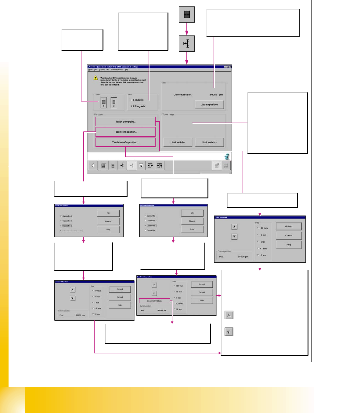
11.3.2 Sitest calibration flow charts
11.3.2.1 Lifting axes
Fig. 11.3 - 2 Overview "Calibration Lifting axes"
Axis
Feed axis
The selected functions are
executed for the feed axis.
Lifting axis
The selected functions are
executed for the lifting axis.
Tower
1/2
Activates the functions
for tower 1 or tower 2.
Info
Current position:
Shows the current position of the activated axis in µm.
Update position
Updates the display for the position of the activated axis.
Travel range
Limit switch +
Moves the selected axis to the limit
switch in order to re-determine the
maximum position which can be
reached. A reference run is then
performed with the axis.
Limit switch -
Moves the selected axis to the limit
switch in order to re-determine the
minimum position which can be
reached. A reference run is then
performed with the axis.
Opens the Teach zero point dialog box
where you can correct the zero point and
then transfers this information.
Every time the button is clicked, the lifting
axis is moved vertically one step downwards
using the increment that you have selected.
Step
Select the desired step size with which to move the
lifting axis.
Current position
Pos.
Displays the position to which the lifting axis moved
during the teaching process.
Apply
Closes this dialog box and accepts the current
position. A reference run is then started.
Every time the button is clicked, the lifting
axis is moved one step upwards using the
increment that you have selected.
Opens the Teach transfer position
dialog box where you can select the
cassette for which the transfer position
is to be taught.
Select the cassette for which the
transfer position is to be taught.
OK
Transfers the selection and opens the
Teach transfer position dialog box.
Open WPTC lock
To check whether the transfer position has been set correctly, the
waffle pack tray carrier is unlocked. It is now possible to push the
waffle pack tray carrier onto the slide rail.
Opens the Teach refill position dialog box
where you can select the cassette for which
the refill position is to be taught.
Select the cassette for which the
refill position is to be taught.
OK
Transfers the data and opens the
Teach refill position dialog box.
1 - 39
Student Guide SIPLACE HF/HF3
Edition 09/2005 11 MTC 2
39
11.3.2.2 Feed axes
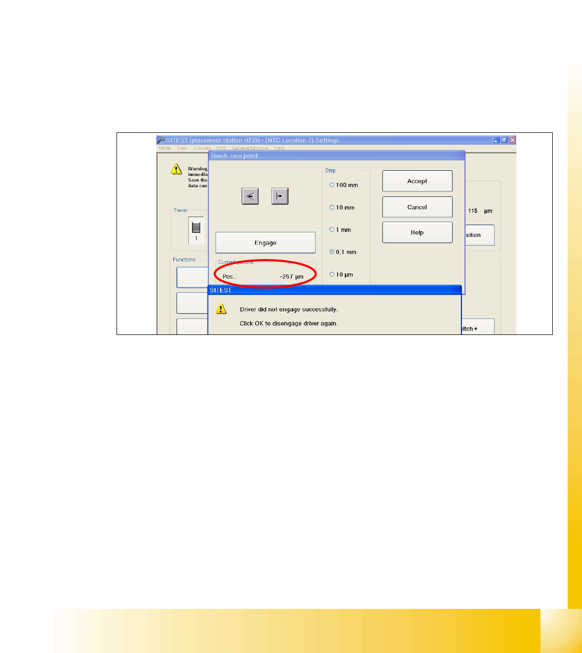
Notes for calibration the zeropoint correction and transfer position into the machine. 11
1a. Calibration of zero point correction: 11
➠ Carry out the relevant preparatory measures (see section 5.2.2 "Preparatory measures").
➠ Select SITEST --> MTC --> Settings
➠ Press the button "Teach zero point"
➠ Check the position of the driver with the button "ENGAGE". In case the driver did not engaged
successfully you must determine the middle of the notch of the waffel pack tray.
The accurate adjustment is described below:
➠ Determine the minimum position of the notch Fig. 11.3 - 3.
Fig. 11.3 - 3 Minimum position
➠ Determine the maximum position of the notch Fig. 11.3 - 4. at which the driver just engages no
more.