SG_FSE_SiplaceHF_HF3_00193901-05_eng.pdf - 第539页
1 - 65 S tudent Guide SIPLACE HF/HF3 Edition 09/2005 1 1 MTC 2 65 1 1.3.5 Converting the power supply T o operate the MTC 2 in the USA or in Japan, the power supply needs to be changed from 400 V , 50 Hz to 208/204 V , 5…
1 - 64
Student Guide SIPLACE HF/HF3
11 MTC 2 Edition 09/2005
64
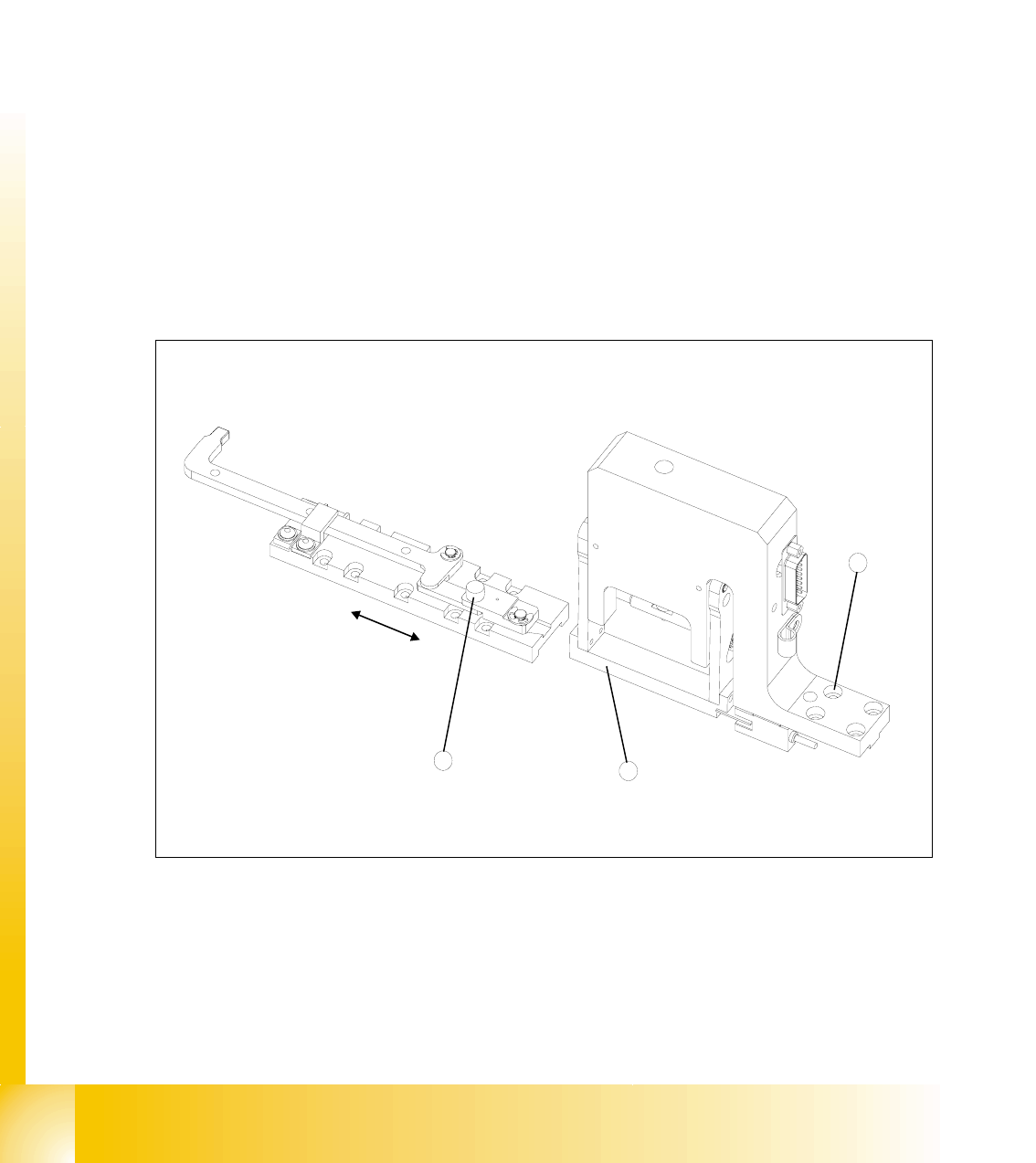
11.3.4.5 Disengaging mechanism
Tools and accessories 11
– 1 set of hexagon socket wrenches
Preparatory measures 11
➠ Empty the MTC 2 completely (see the User Manual).
➠ Move the feed axis into the zero position (see section11.3.2.2 ) and engage the driver in the
WTC.
Setting the disengaging mechanism 11
➠ Move the driver over the belt until it lies outside the disengaging mechanism.
➠ Check that the driver in its dead center position engages centrally with the disengaging
aperture when it is moved back.
➠ When the guide roller is pushed through the middle of the aperture, set the position of the
aperture with the 4 securing screws of the disengaging mechanism.
Fig. 11.3 - 26 Setting the disengaging mechanism
Key
1 Driver guide roller in dead center position
2 Disengaging mechanism aperture
3 Disengaging mechanism securing screws
2
3
1
1 - 65
Student Guide SIPLACE HF/HF3
Edition 09/2005 11 MTC 2
65
11.3.5 Converting the power supply
To operate the MTC 2 in the USA or in Japan, the power supply needs to be changed from 400
V, 50 Hz to 208/204 V, 50/60 Hz.
NOTE
To convert the power supply from 208/204 V to 400 V, the same procedure must be carried out in
the reverse order.
Tools and accessories 11
– 1 set of screwdrivers
– 3 additional bridges
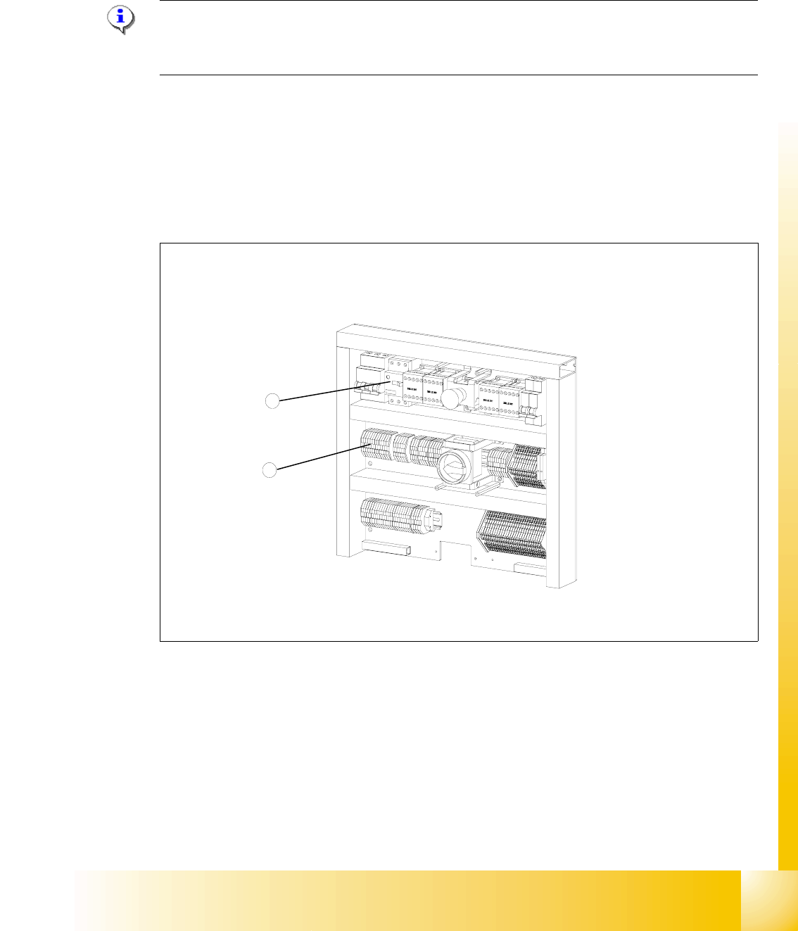
11.3.5.1 Procedure
Fig. 11.3 - 27 Electronics board
Key
1 Bridges on the voltage distributor terminal X01
2 Motor protection switch
2
1
1 - 66
Student Guide SIPLACE HF/HF3
11 MTC 2 Edition 09/2005
66
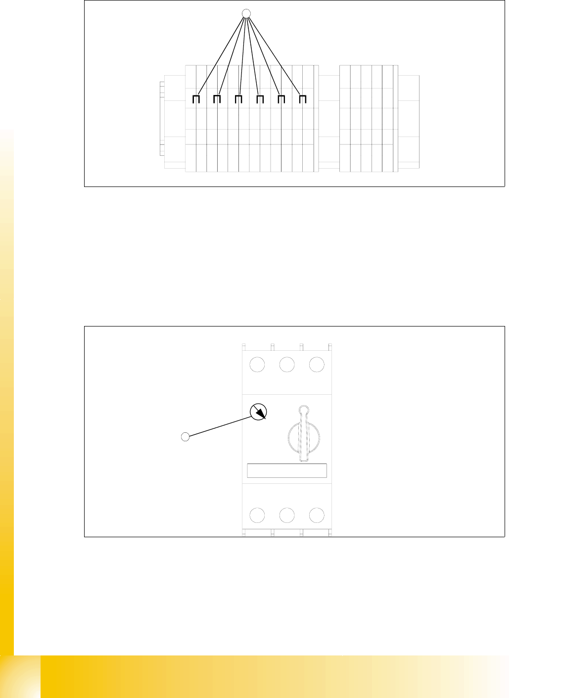
11.3.5.2 Voltage distributor terminal X01
11
Fig. 11.3 - 28 Voltage distributor terminal X01
Key
1 Bridges on the voltage distributor terminal X01
➠ Removing the three bridges between 2-3, 6-7 and 10-11.
➠ Connect the six bridges between 1-2, 3-4, 5-6, 7-8, 9-10 and 11-12.
11.3.5.3 Motor protection switch
11
Fig. 11.3 - 29 Motor protection switch
Key
1 Rotary regulator of the motor protection switch
➠ Do not switch the rotary regulator of the motor protection switch, if you converting the power
supply. It is always 3.5 A.
-X01
1
2
3
45
6789
10
11
12
11
11
3,5A
5,0A