SG_FSE_SiplaceHF_HF3_00193901-05_eng.pdf - 第265页
1 - 65 S tudent Guide SIPLACE HF/HF3 Edition 09/2005 6 Colle ct &Place-Head / DLM2 65 6.4.6 Belt tension Z-axis Please Note: The measuring point of the measur ing pin must be in the middle of the two deflection pulle…
1 - 64
Student Guide SIPLACE HF/HF3
6 Collect &Place-Head / DLM2 Edition 09/2005
64
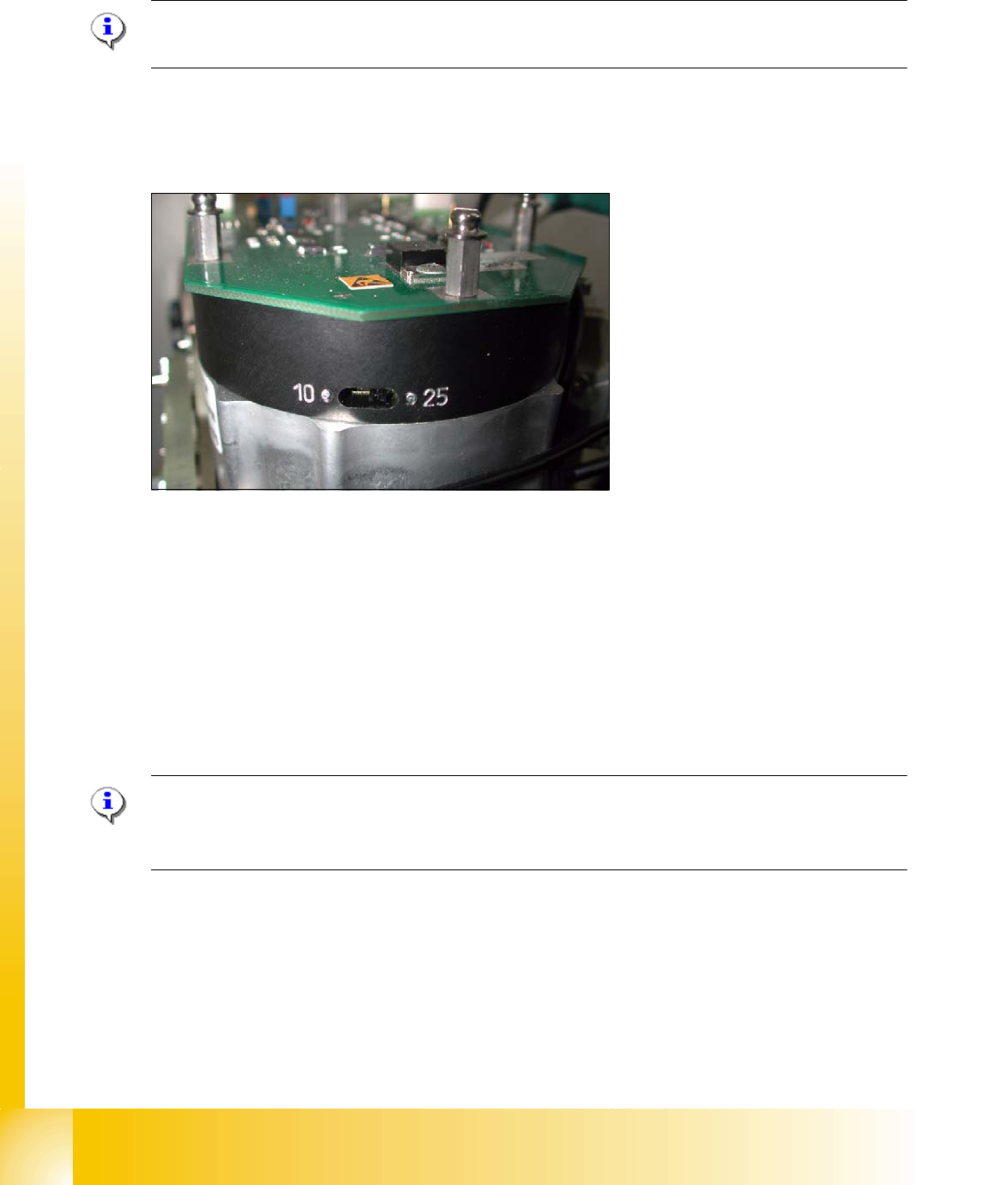
6.4.4 Setting star axis resolution
The switch for the star axis resolution is directly beneath the C&P head on the star motor. 6
Check the setting of this switch (arrow): 6
Please Note:
Only setting the switch, if the machine power is off.
– HS-60 and S-27 HM: Switch position 10
– HF-machines: Switch position 25
6
Fig. 6.4 - 12 Setting the resolution on the star axis
6.4.5 Setup of the Digital Rotary Transducer of the DP - Axis
➠ Remove sleeve 1 and insert the Star zero point gauge, in order to mechanically fix the Star.
➠ Now, remove sleeve 4 or the sleeve 2 for the 6 segment C&P head as well and align the trans-
ducer.
➠ With the help of a parallel pin, set the rotary transducer of the DP - axis to 1.5 mm, parallel to
the glass pane of the segments.
Please Note:
A parallel pin of 1.4 mm must easily fit through the gap, a parallel pin of 1.6 mm must be too large
to fit.
1 - 65
Student Guide SIPLACE HF/HF3
Edition 09/2005 6 Collect &Place-Head / DLM2
65
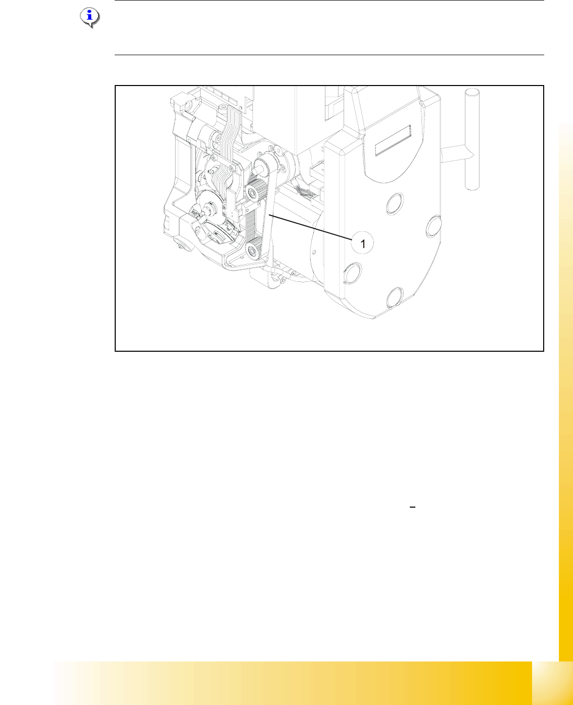
6.4.6 Belt tension Z-axis
Please Note:
The measuring point of the measuring pin must be in the middle of the two deflection pulleys.
The measuring pin should be at a maximum distance of 2 - 3 mm, from the toothed belt. 6
Fig. 6.4 - 13 Measuring point for the belt tension of the Z-axis
Legend Fig. 6.4 - 13
(1) Measurement point for the belt tension
➠ Attach the measuring head in front of the toothed belt (1) .
➠ Strike the toothed belt, to reach a stimulation of vibration of the open ended toothed belt.
➠ Stretch the belt over the fastening of the driving motor (compare: service manual) if the
frequency of the belt tension does not reach a value of
280 Hz + 10 Hz.
➠ Repeat these instructions until the belt tension is correct.
1 - 66
Student Guide SIPLACE HF/HF3
6 Collect &Place-Head / DLM2 Edition 09/2005
66
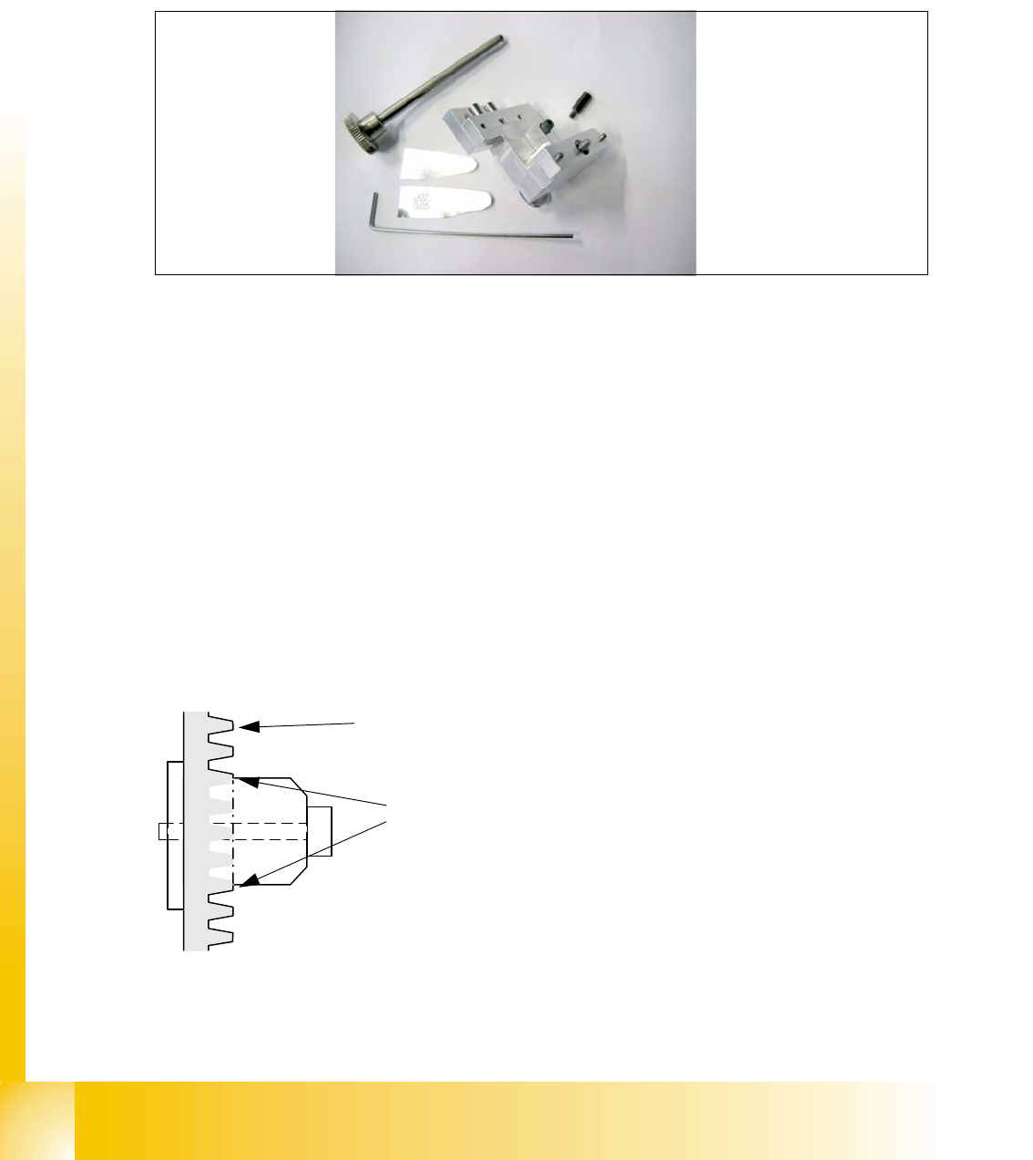
6.4.7 Adjusting the Stop for the Z-Axis
6.4.7.1 Tools and Equipment
– Set of DIN 911 Allen keys
– Gauge for Z-limit stop, item no.03019865-01
Fig. 6.4 - 14 Gauge for Z-limit stop
6.4.7.2 General
With the softwareversion 503.02 and higher the calculation of the zero point correction of the
Z-axis is done with the star in a position of 2700 digits. During the reference run the Z axis (star
axis position +2700 digits) now moves down and up into the aperture. To ensure that the Z axis is
located correctly in the center of the raceway/aperture, it must be possible for the Z axis to move
into the aperture up to the limit stop. This is only possible if the Z limit stop is set correctly.
Preconditions: 6
Before you start with the setting please check the followings:
– Belt tension Z-Axis
– Correctly mounted clamping device on the Z-axis belt.
Fig. 6.4 - 15 Clamping device Z-axis
You ensure, so that the clamping device is firmly fixed between the teeth of the drive belt.
Tooth on the drivebelt
Clamping device between the
teeth of the drive belt