SG_FSE_SiplaceHF_HF3_00193901-05_eng.pdf - 第358页
1 - 10 S tudent Guide SIPLACE HF/HF3 7 TWIN-Head Edition 09/2005 10 7.6.3.2 T est setup with Axis testbox Fig. 7.6 - 5 T est setup w ith axis testbox Please Note:: Use an RC - filter to record the current c urve. Measure…
1 - 9
Student Guide SIPLACE HF/HF3
Edition 09/2005 7 TWIN-Head
9
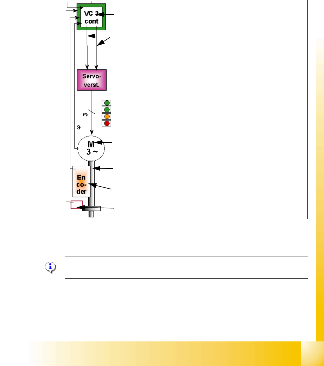
7.6.3 Axis control TWIN- Head Z-axis
The Z axis is driven with a 3 phase AC linear motor with an intermediate circuit voltage of 60V.
The control of the axis occurred with two control signals of the VC3 (dephasing 120°) controller
I
nom "W" and I nom "U". The third phase is calculated at Servo amplifier.
Fig. 7.6 - 4 Axis control Z-axis TWIN- head
7.6.3.1 Check the dynamic of Z-axis
Please Note:
For check the dynamic please use the official Adjustment manual.
Axis board A363 with VC 3 Controller (VC = Velocity Commutation)
Control signals I
soll "W" and I soll "U"
Servo board control directly the linear motor, Intermediate (DC) voltage cir-
cuit is 250V.
LED‘s on Servo board:
– Power supply ON
– Servo enable, it the enable signal from the axis board.
–Display I
RMS limit shorter than 2,5 s.
– Error: Over voltage, -current, -temperature longer than 2,5 sec.
3 Phase AC linear motor with integreted temperatur sensor.
Between motor and incremental scale exist a fixed mechanically connec-
tion.The incremental encoder is fixed on the frame of the TWIN- head.
Incremental encoder: Transmitted the correct position to the axis board and
is the only feedback signal to control the motor (Track signals).
Force sensor
1 - 11
Student Guide SIPLACE HF/HF3
Edition 09/2005 7 TWIN-Head
11
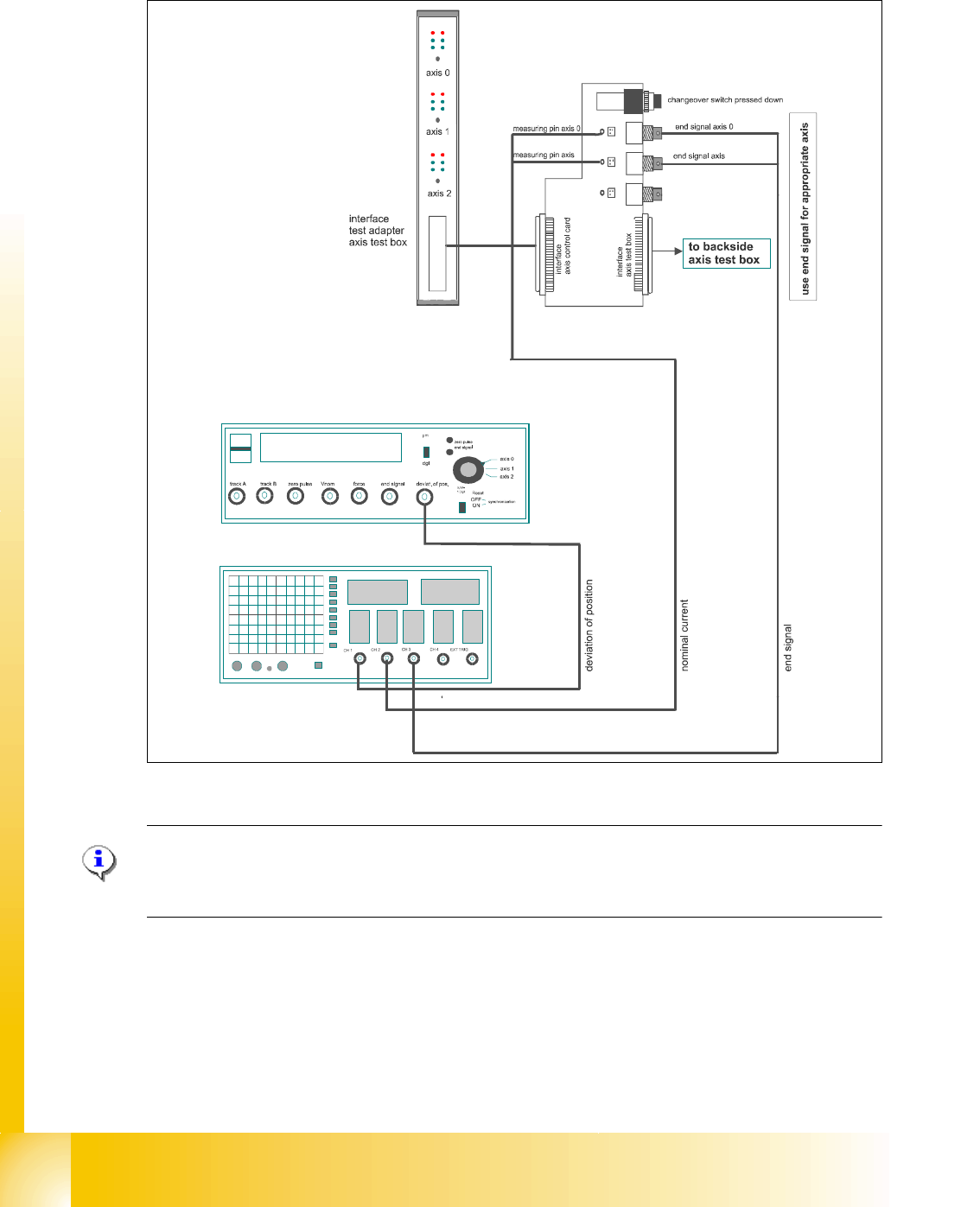
7.6.3.3 Test setup with SAT-Box
Please Note::
For checking of the dynamics with the aid of the SAT-Box please use the official Adjustment ma-
nual. 7
Fig. 7.6 - 6 Test set up SAT-Box
Legend outputs Siplace Axis Tester to oscilloscope channels
The Axis dynamic of the Z axis is checked with continuos run in free space. At V nominal output
of the Axis tester pass a motor current signal. The uncommutated nominal current signal (Signal3)
show the friction of the axis system. If the current is increased it show also increased friction.
The positioning time for the Z axis is 84 ms +/-2ms.
(1) Nominal current (Vreg)
not connected to the scope for HF
(2) uncommutated nominal current
connect to CH2
(3) Deviation of position connect to CH1 (4) End signal connect to CH 3
Axis unit error
Servo ON
Initialize
Counter error
Zero puls
End signal
Interface:
Test adapter,
Axis test box,
SAT-Box
2
4
1
3