SG_FSE_SiplaceHF_HF3_00193901-05_eng.pdf - 第376页
1 - 8 S tudent Guide SIPLACE HF/HF3 8 Component handling Edition 09/2005 8 8.2.2.4 Docking unit The docking unit is fixed with a special screw to the machine so that the accuracy for picking up of small components from t…
1 - 7
Student Guide SIPLACE HF/HF3
Edition 09/2005 8 Component handling
7
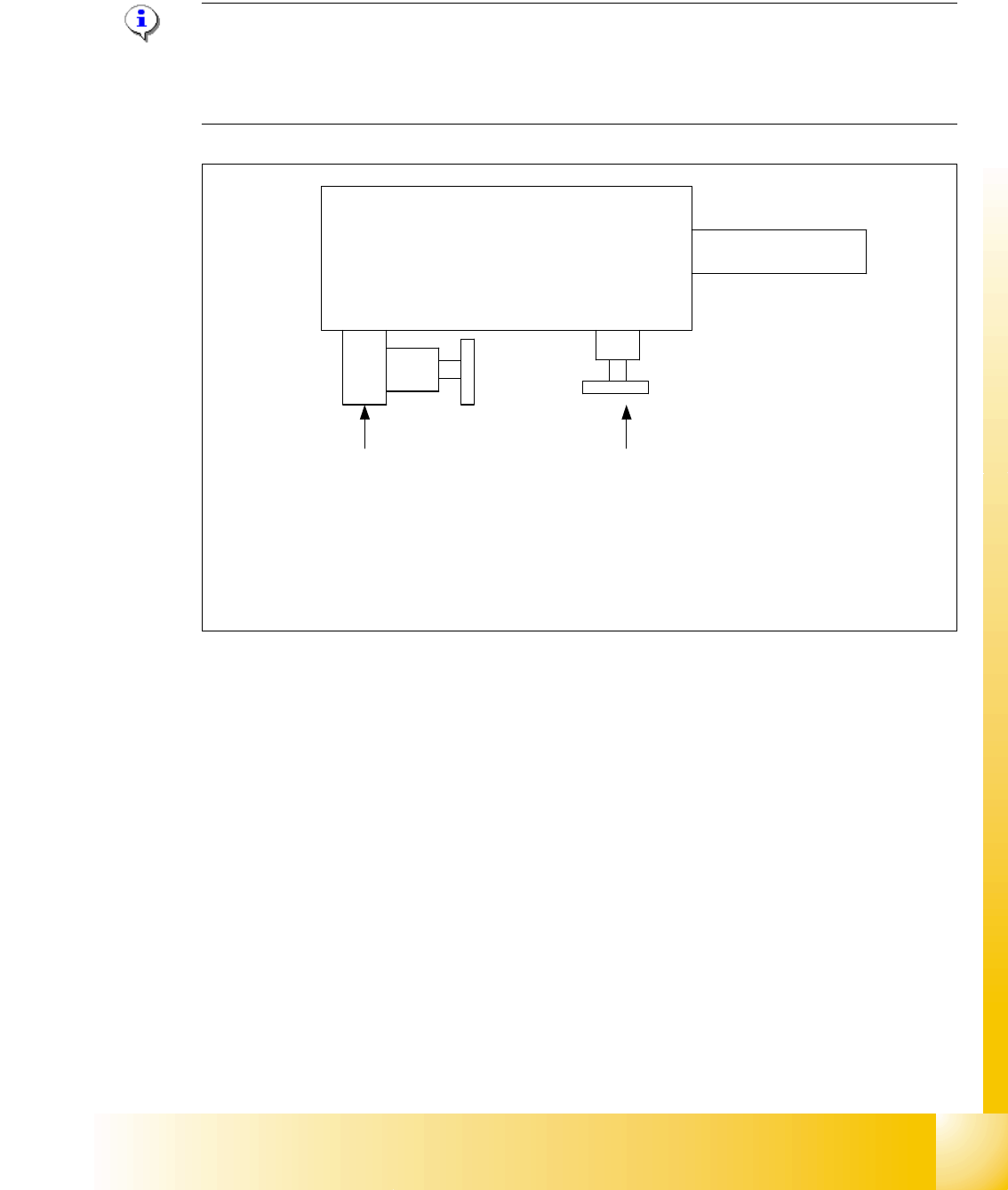
8.2.2.3 Adjustment pneumatic cylinder
The movement of the CAM-disks at the docking unit, left and right side can be individually adjus-
ted at the round cylinder
Note:
If you adjust the pneumatics cylinder is to be ensured that the COT is moved in parallel into the
docking unit. The docking and undocking procces of the COT should be set to
approx. 2 seconds.
Fig. 8.2 - 3 Adjustment the pneumatic cylinder on the docking unit
Valve setting
Time characteristic for
docking the COT
Valve setting
Time characteristic for
undocking the COT
Pneumatic cylinder
Docking unit
Piston rod
Setting valve anticlockwise: Increase the time for the docking and undocking process
Setting valve clockwise: Reduce the time for the docking and undocking process
1 - 8
Student Guide SIPLACE HF/HF3
8 Component handling Edition 09/2005
8
8.2.2.4 Docking unit
The docking unit is fixed with a special screw to the machine so that the accuracy for picking up
of small components from the COT is guaranteed. These screw had to be fixed first before the
other screws when mounting the docking unit. (Necessary in case of changing the docking unit
COT to MTC 2 or vise versa).
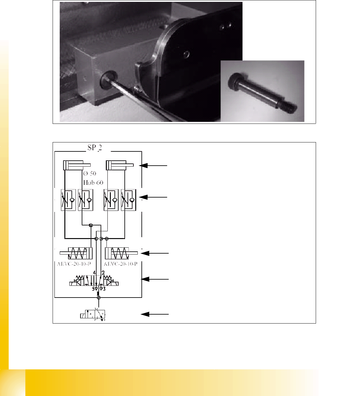
Fig. 8.2 - 4 Special screw on the docking unit
Fig. 8.2 - 5 Pneumatic diagram docking unit
Pneumatic cylinder for move the cam disks. That
means the component table plate will move hori-
zontal 43mm and 20 mm vertical into the machine.
Throttle valves for adjust the speed of the pneu-
matic cylinders (Time adjustment). The time for ad-
just should be approx. 2-3 sec.for dokking and
undocking the COT. Check the time without COT.
Pneumatic cylinders for ejection the COT during
the undocking procedure.
5/2 Way valve for control the pneumatic cylinder.
Safety valve in case of electrical faults
1 - 9
Student Guide SIPLACE HF/HF3
Edition 09/2005 8 Component handling
9
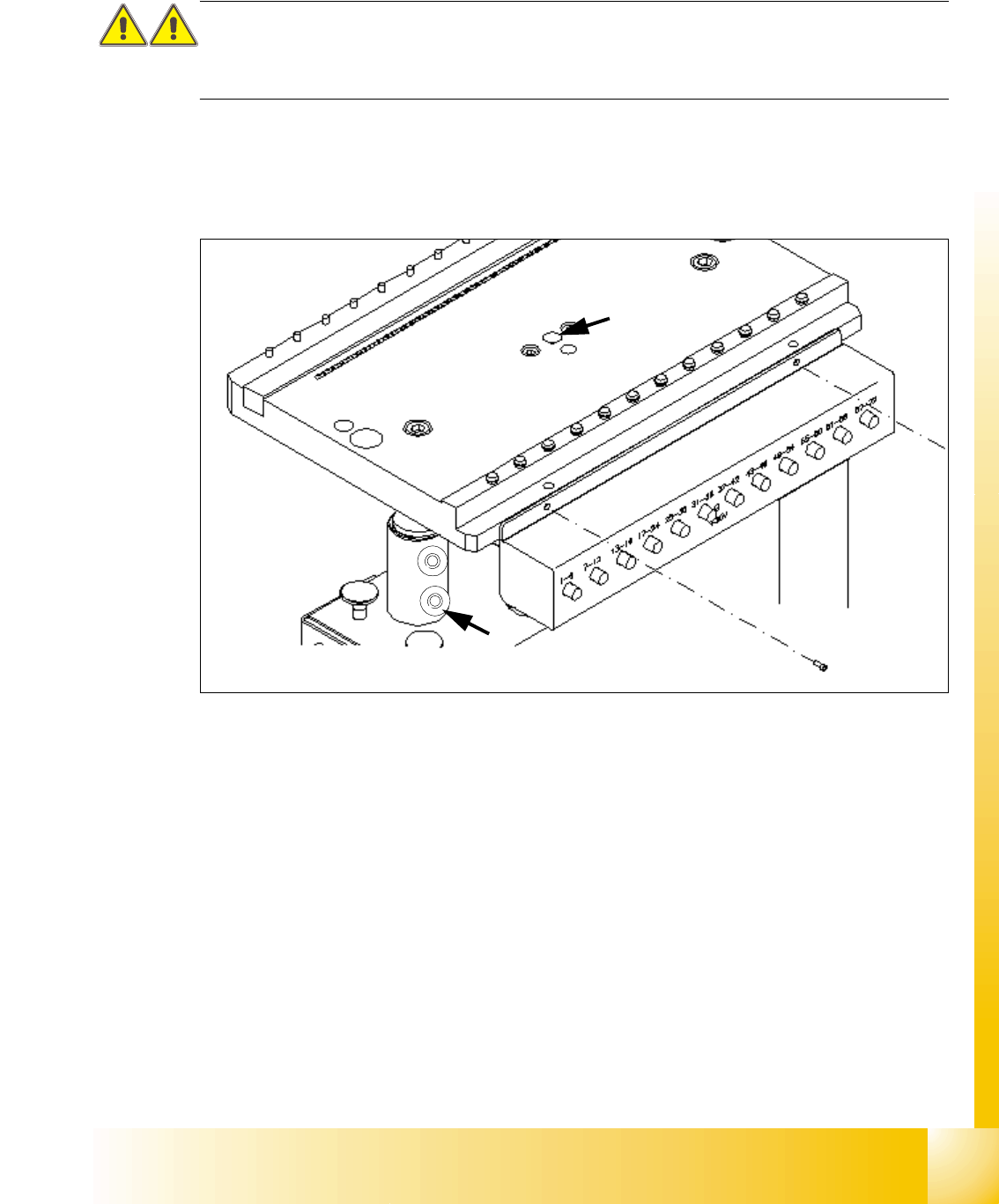
8.2.3 Adjustment the COT height
This task requires 2 more persons to increase and decrease the COT height.
CAUTION:
Use always the eye-bolt to fix the component plate, independend if you increase or reduce the
component table height, otherwise you may hurt your fingers.
➠ Attach the hooks of the lifting device to the eye-bolt (2) and fix the lifting plate.
➠ (at model 1) losen the 4 fixing scrwews on each of the 2 COT frame sides.
➠ (Model 2) Remove the 2 cotter pins from the sleeve shaft.
Fig. 8.2 - 6 Adjusting the COT height
Legend
Increasing and reducing the COT height 8
➠ Raise the component table top part until to rich the desired position of the height from the com-
ponent table.
➠ Put back the 2 cotter pins into the drilling hole of the sleeve shaft.
respective fix the fixing screws on each COT frame side.
➠ Unscrew the eye-bolt from the component trolley bed.
➠ Now, COT height is adjusted.
(1)Drilling hole for eye-bolt 2. Hole for the cotter pins
1
2