SG_FSE_SiplaceHF_HF3_00193901-05_eng.pdf - 第270页
1 - 70 S tudent Guide SIPLACE HF/HF3 6 Collect &Place-He ad / DLM2 Edition 09/2005 70 6.4.10 Adjustment of mechani cal Position of V alve Drives ➠ If the new valve plungers are used (s. Fig. 6.4 - 20 ), proceed as fo…
1 - 69
Student Guide SIPLACE HF/HF3
Edition 09/2005 6 Collect &Place-Head / DLM2
69
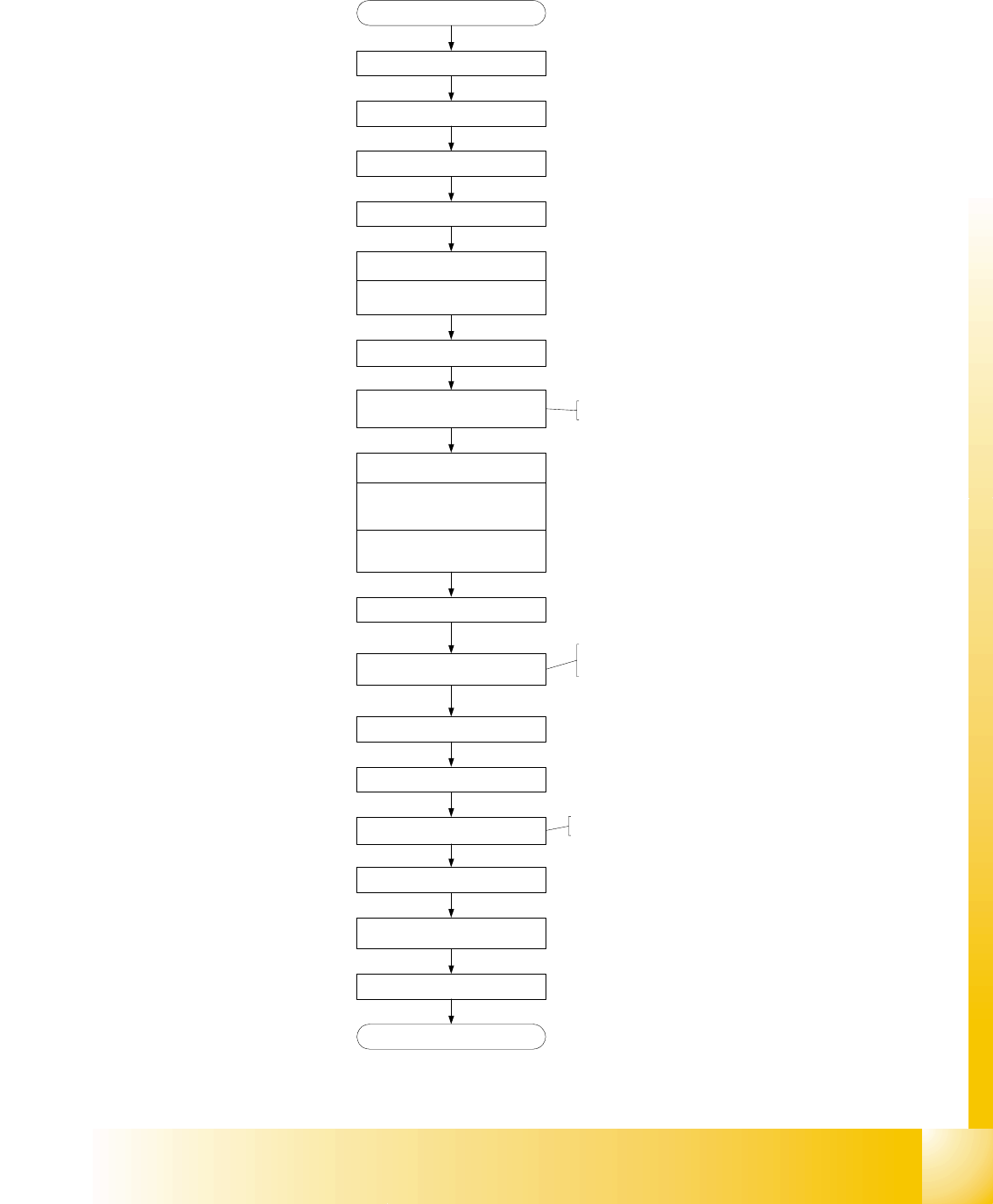
6.4.9 Determination of Zero Point Correction Star-Axis C&P Head
Fig. 6.4 - 18 Flow chart zero point correction
Menue C&P Heads
Select referring C&P Head
Menue Axes
Select Star axis
Positions
Zero point correction (ZPC) = 0
edit and accept
Axis reference run
disable Star / Z* Axis at axis
controller
Remove sleeve from segment 1
Turn segment 1 to bottom position
Mount Star axis Zero point gauge,
Insert fixing pin into gauge
DLM2 lower Z-Axis, that fixing pin
engage at segment
Select DP- and Star-Axis again
Enter actual position as new
Zero point correction (ZPC)
*
Remove Star zero point gauge
Insert sleeve
Enable Star (Z*) Servo
Execute Axis reference run
check position of the new Zero point-
correction (Segment 1 down)
Save machine data
End
start SITEST
* for DLM2 at HF-Machine:
* ZPC for HF-Machine: divide
actual Position by 2.5
* for DLM2 at HF-Machine:
1 - 70
Student Guide SIPLACE HF/HF3
6 Collect &Place-Head / DLM2 Edition 09/2005
70
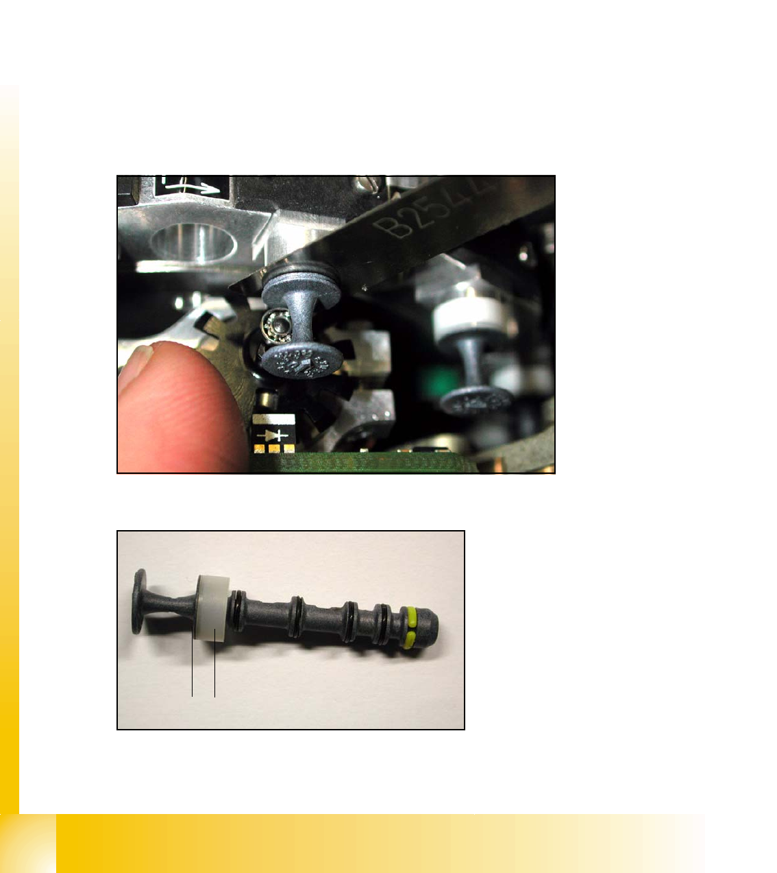
6.4.10 Adjustment of mechanical Position of Valve Drives
➠ If the new valve plungers are used (s. Fig. 6.4 - 20), proceed as follows:
– Take out one valve plunger and remove the plastic bushing
(2).
– Insert the plunger without bushing and carry out the following steps on this segment:
➠ Set the motor position of the valve drives "Pick-up / Placement" and "Ejection" according to the
figure below.
➠ Insert the distance gauge (0.2 mm) between valve plunger and valve casing.
➠ Turn the valve drive to 90° degrees, opposite to its initial position. The excentric of the valve
drive will just touch the inner flange of the valve.
➠ Fix the motor of the valve drive in this position.
➠ Don’t forget to refit the plastic bushing on the plunger.
6
Fig. 6.4 - 19 Mechanical position of the valve drive
6
Fig. 6.4 - 20 New Valve plunger, item.no:00351498-03
2
1
1 - 71
Student Guide SIPLACE HF/HF3
Edition 09/2005 6 Collect &Place-Head / DLM2
71
6.4.11 Air Pressure Values
6.4.11.1 Tools and Devices
– A set of slotted screw drivers
– Compressed air testing device
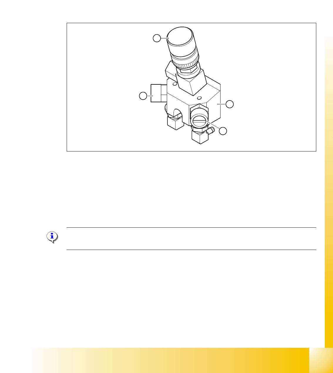
6.4.11.2 Adjustment of Air Pressure Values
6
Fig. 6.4 - 21 Adjustment of air pressure values
LEGEND:
(1) Forced air unit
(2) Solenoid valve for air kiss
(3) Adjustment valve for the reject circuit
(4) Adjustment valve for the pick - up / placement circuit
Please Note
:Use a nozzle type 904 or 914 to adjust the air kiss. 6
4
1
2
3