SG_FSE_SiplaceHF_HF3_00193901-05_eng.pdf - 第67页
1 - 41 S tudent Guide SIPLACE HF/HF3 Edition 09/2005 2 Overview 41 2.2.17 Conveyor system 2.2.17.1 General The Siplace HF comes st andard with a single conveyor . The dual conveyor system is available as an option. Depen…
1 - 40
Student Guide SIPLACE HF/HF3
2 Overview Edition 09/2005
40
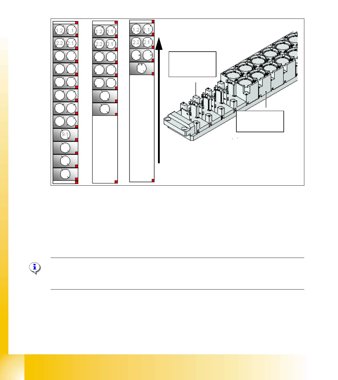
2.2.16.2 Nozzle changer Twin head
The Siplace HF is supplied with a standard nozzle changer for the Twin head. The nozzle changer
is installed in section 3.
The nozzle changer for a Twin head consists of the standard module as 3 garage, each with two
nozzle and one garage for one special nozzle (see Fig. 2.2 - 29).
Fig. 2.2 - 29 Nozzle changer Twin head
1. Standard nozzle changer
2. extended nozzle changer
3. completed nozzle changer
Please Note:
The configurations mentioned above could be changed as required and magazines for standard
and special nozzles can be added one by one.
Magazin for 1
special nozzle
Magazin for 2
standard nozzle
Transport direction

1 - 41
Student Guide SIPLACE HF/HF3
Edition 09/2005 2 Overview
41
2.2.17 Conveyor system
2.2.17.1 General
The Siplace HF comes standard with a single conveyor. The dual conveyor system is available as
an option. Depending on your requirements you can choose the left or right conveyor side as a
fixed conveyor side.
In the Processing Area, the PCB board will be clamping from the botton side against the fixed
holder on the conveyor system. Therefore, the distance between the top of the PCB board and
the C&P Head will always be the same for every PCB board, regardless of the PCB thickness.
Accordingly, the placement rate is not dependent on the PCB board thickness. Furthermore, the
fiducial recognition can be optimized, because the distance between the top of the PCB board and
the PCB camera will always be the same. This will ensure the focuses will always remain the same
when the fiducial shape is imaged optically on the CCD chip of the PCB camera.
The 12 C&P head can handle components with a maximum heigh of 6 mm and the 6 C&P head
can handle components with a maximum heigh of 8,5 mm.
The conveyor system use SMEMA or SIEMENS(option) interface and can be adjusted to following
heights 830, 900, 930 or 950 mm.
The transferring of the PCB boards is checked and controlled with light barriers which consist of
a transmitter module and a receiving module. When the PCB board arrives at the placement po-
sition, it is stopped at the precise position with the aid of a Laser beam and then it is clamped from
the bottom side.
Clamping 2
The PCB will be lifted for placment components and pressed against to the PCB holder. During
start of the lifting table, the PCB is lifted and clamping with the complete transportation drive unit.
Therefore the placement level is constant and independent of the thickness from the PCB.
PCB`s with a length of 450 mm (368mm for the HS60) will be clamped and supported by the lifting
table. However, any lenght over 450 mm (368mm for HS60) will not be supported by the lifting
table.
Width Adjustment 2
The width adjustment occurs with one motor via a job from the Siplace Pro computer. Different
widths for a double conveyor for the two conveyor tracks are possible. The width adjustment oc-
curs by means of stepping motor so that the adjustment of the new PCB width can occur indepen-
dent from other machine components(e.g. axis gantry). Now we don‘t use the BERO for the width
adjustment on the conveyor side.
The width of each PCB conveyor system (Conveyor1 and 2) will be adjusted with 3 drive pins
(pneumatic cylinder), they are installed under the input , intermediate and output conveyors. The
drive pins will be move continuously and parallel to left and rihgt side with a recirculating spindle,
one belt and a step motor.

1 - 42
Student Guide SIPLACE HF/HF3
2 Overview Edition 09/2005
42
Control the PCB inside the conveyors 2
The PCB will be checked with light barriers (transmitter module and a receiving module). The light
barriers are positioned above the transportbelts and they point past the transportbelt.The light bar-
riers stopps the PCB in the input conveyor, intermediate conveyor and output conveyor.
With the signal from the light barrier the brake application of the DC motor is starting, only in the
placement area. The PCB move in a unchangable time period (100ms) with their reduced speed
to the stopper position(Laser) that control via software. Indepent of heavy and light PCB board we
start the brake application to the right time so that we move always approx. 100ms to the stopper.
PCB Stopper 2
The PCB in the placement area will be stop with a laser light barrier. The laser light barrier looks
at the front edge of the PCB and stop them. In this case we do not have a shock against the stop-
per.
The position accuracy of the PCB is +/-0,5mm.
– Mechanical stopper for long boards up to 610mm is an option
Lifting table 2
In each placement area we have one or two independent working lifting tables (dual/single con-
veyor). The lifting table drive is working indirectly via pneumatic cylinder controlled of a 5/3 way
valve. Different thickness of PCB is automatically compensate. The guide for the lifting table plate
in the vertical direction (up/down) is defined at four point. The lifting distance is determined via a
incremental system.
The upper position will be controlled over the measurement system with a incremental encoder
and via the current of the transport motor.
The lower position will be checked with the measurement system and a BERO on the pneumatic
cylinder.
Additional we check the time which we need in both directions.
The clearance under the PCB is 40mm.
You can not use the old 74 mm high PCB supports on the HF machines.
The dual conveyor can be used as an single conveyor when you move the conveyor rails of track
2 to the limits (depend on the Softwareversion 505).