SG_FSE_SiplaceHF_HF3_00193901-05_eng.pdf - 第254页
1 - 54 S tudent Guide SIPLACE HF/HF3 6 Collect &Place-He ad / DLM2 Edition 09/2005 54 6.4.1.5 Stepping motor board The stepping motor board for the valve driver s and the swivel function on the DP station is mou n- t…
1 - 53
Student Guide SIPLACE HF/HF3
Edition 09/2005 6 Collect &Place-Head / DLM2
53
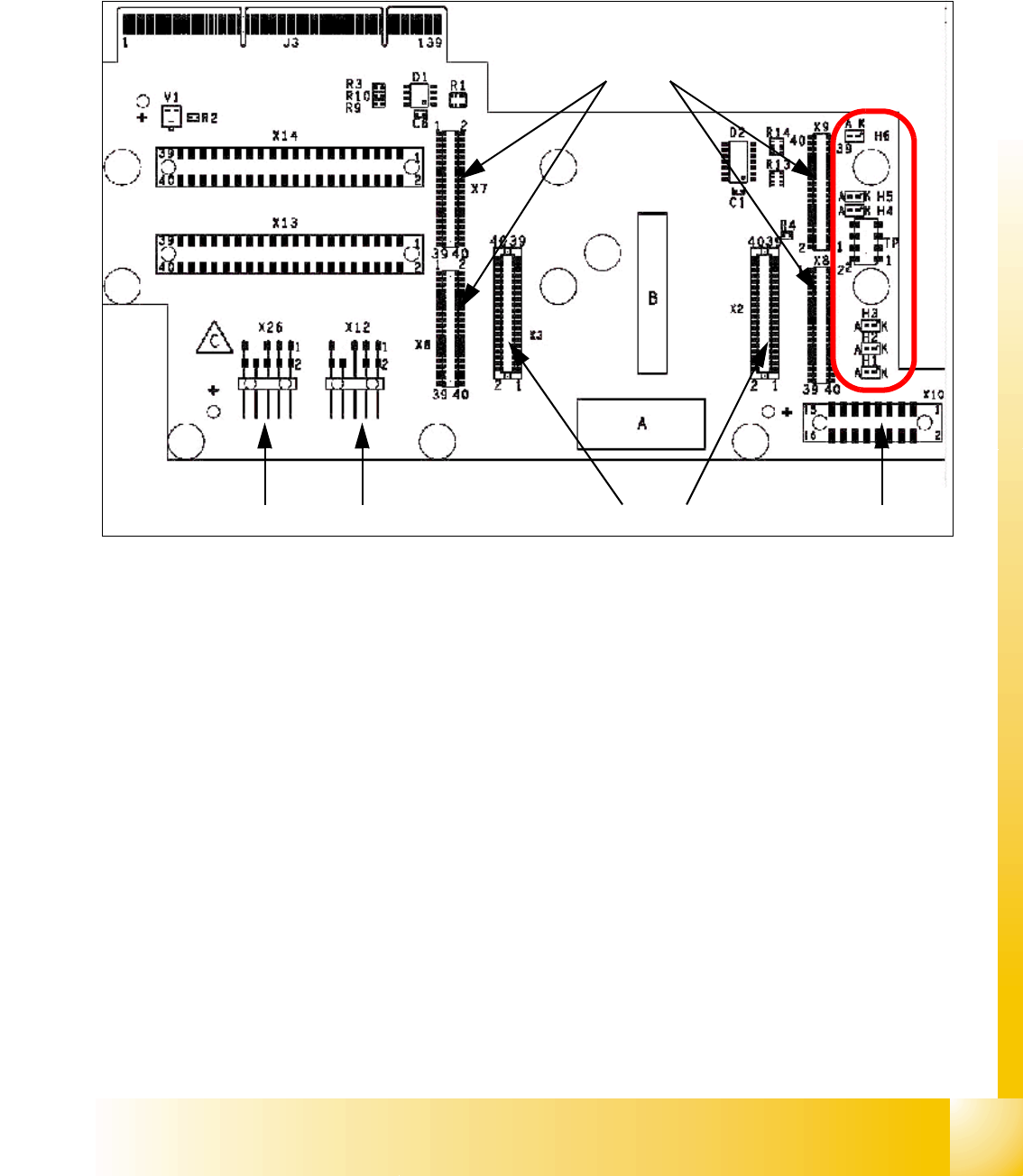
6.4.1.4 Headadapter for 6/12 C&P head
At the head modularity we can use the same head adapter for the 6 and 12 segment C&P heads.
The head adapter must be exchanged if you mounting the Twin head.
Fig. 6.4 - 4 Headadapter for 6/12 C&P head
1. X6 -X9 Connector for CAN Prozessor-board’ 80C515C 8Bit
2. X2/X3 Connector for the stepping motor board
3. X10 Connector vacuum board
4. X12 Dp station (motor, track signale)
5. X26 Option component sensor
6. X13/14 connector for the flat cable to the intermediate distribution boardr
7. Connector to the headinterface
Description LED‘s: 6
– LZOS Light barrier Z-axis upper stop
– LZUS Light barrier Z-axis down position
– LSM Stepper motor board not connected
– LSZD Light barrier Swivel in for turning at DP-station
– LSVZ Light barrier Vacuum / air kiss Z-axis
– LSVA Light barrier Vacuum / air kiss reject position
1
2
45
3
6
7
LED‘S
1 - 54
Student Guide SIPLACE HF/HF3
6 Collect &Place-Head / DLM2 Edition 09/2005
54
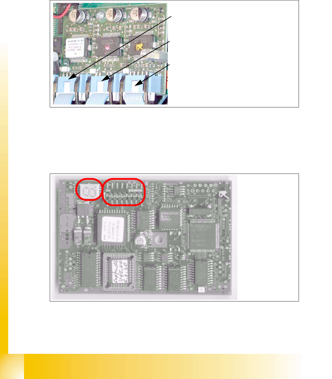
6.4.1.5 Stepping motor board
The stepping motor board for the valve drivers and the swivel function on the DP station is moun-
ted onto the head adapter below the CAN processor board 80C515C. Is the board missing the
LSM LED at the head adapter is ON. In this case the CAN-Bus-Processor board can not fixed.
Fig. 6.4 - 5 Stepping motor board
6.4.1.6 CAN Processor board 8 Bit 80C515C on the head adapter C&P
Fig. 6.4 - 6 CAN Processor board
2
3
1
Stepping motor rejectposition
(for S/F. HS and HF-machine)
Stepping motor pick up-, placement-
(and reject position HF/HF3)
Stepping motor DP-axis
Description
DIP-Switches and
7 Segment display
see below.
1 - 55
Student Guide SIPLACE HF/HF3
Edition 09/2005 6 Collect &Place-Head / DLM2
55
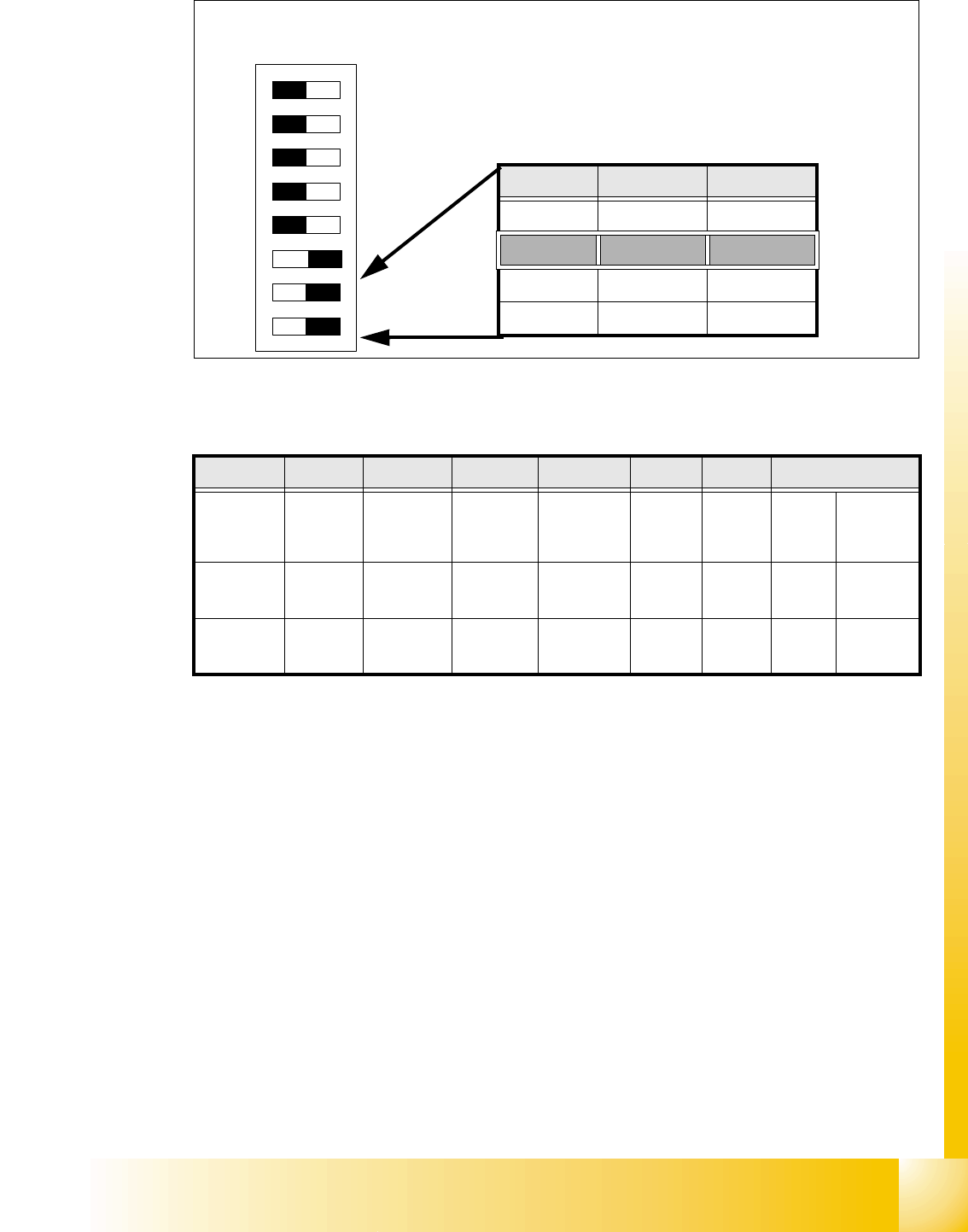
6.4.1.7 Switch position on the head board
6
Fig. 6.4 - 7 Table: DIP-Switches
The wiring of the switch depends on the placement machine involved: 6
Jumper 1: ON -> CAN matching resistor on the placement head is set
(S-20, F4, F5), S-23,
S-25 HM, F5 HM.
OFF ->CAN_matching resistor is not wired on the head (
HS/HF default)
Jumper 2: ON -> Setting during the download
OFF -> Default status
Jumper 3: ON -> Test mode
OFF -> Default status
Jumper 4: ON -> Test mode (setting of CAN ID)
OFF -> Default status
Jumper 5: ON -> Default status
OFF -> Switch off CAN_Objects component-,LP-Vision und IC-head on the
modulare Head-FW (only for SIPLACE_HF)
Jumper 6: ON -> Default status
Jumper 7, 8: CAN_ID:
DIP Switch
ON
78123456
Gantries Switch 7 Switch 8
Gantry 1 ON ON
Gantry 2 ON OFF
Gantry 3 OFF ON
Gantry 4 OFF OFF
Standard OFF OFF OFF OFF ON ON CAN_Addresse
Switch
position
1
CAN_R120
2
EPROM_WE
3
Test_Mode
4
CAN_ERR_
SWITCH
5
Jumper 5
6
Jumper 6
7
CAN_ID1
8
CAN_ID0
ON X
see
above
see above
OFF X X X X X
see
above
see above