SG_FSE_SiplaceHF_HF3_00193901-05_eng.pdf - 第200页
1 - 4 S tudent Guide SIPLACE HF/HF3 Contents Edition 09/2005 4 6.8.5.1 Star brake . . . . . . . . . . . . . . . . . . . . . . . . . . . . . . . . . . . . . . . . . . . . . . . . . . . . . 10 7 6.8.5.3 Vacuum distributor …

1 - 3
Student Guide SIPLACE HF/HF3
Edition 09/2005 Contents
3
6.4.7.2 General. . . . . . . . . . . . . . . . . . . . . . . . . . . . . . . . . . . . . . . . . . . . . . . . . . . . . . . . 66
6.4.7.3 Settings . . . . . . . . . . . . . . . . . . . . . . . . . . . . . . . . . . . . . . . . . . . . . . . . . . . . . . . 67
6.4.8 Light Barrier, Bottom Position . . . . . . . . . . . . . . . . . . . . . . . . . . . . . . . . . . . . . . . . . . 68
6.4.9 Determination of Zero Point Correction Star-Axis C&P Head . . . . . . . . . . . . . . . . . . 69
6.4.10 Adjustment of mechanical Position of Valve Drives . . . . . . . . . . . . . . . . . . . . . . . . 70
6.4.11 Air Pressure Values. . . . . . . . . . . . . . . . . . . . . . . . . . . . . . . . . . . . . . . . . . . . . . . . . 71
6.4.11.1 Tools and Devices . . . . . . . . . . . . . . . . . . . . . . . . . . . . . . . . . . . . . . . . . . . . . . 71
6.4.11.2 Adjustment of Air Pressure Values. . . . . . . . . . . . . . . . . . . . . . . . . . . . . . . . . . 71
6.4.11.3 Adjustments of Air Pressure Values with the Compressed Air Testing Device 72
6.4.12 Other Mechanical Adjustments on the Star. . . . . . . . . . . . . . . . . . . . . . . . . . . . . . . 73
6.5 Nozzle changer. . . . . . . . . . . . . . . . . . . . . . . . . . . . . . . . . . . . . . . . . . . . . . . . . . . . . . . . . . . . . . . . . 75
6.5.1 Nozzle changer for 12 segment C&P head . . . . . . . . . . . . . . . . . . . . . . . . . . . . . . . . 75
6.5.2 Nozzle changer for 6 segment C&P head. . . . . . . . . . . . . . . . . . . . . . . . . . . . . . . . . 76
6.5.3 Control nozzle changer on the C&P heads . . . . . . . . . . . . . . . . . . . . . . . . . . . . . . . . 77
6.6 Axis control . . . . . . . . . . . . . . . . . . . . . . . . . . . . . . . . . . . . . . . . . . . . . . . . . . . . . . . . . . . . . . . . . . . 79
6.6.1 Overview Axis control Star-, Z- and DP-Axis. . . . . . . . . . . . . . . . . . . . . . . . . . . . . . . 79
6.6.1.1 Overview positioning time 12 segment C&P head . . . . . . . . . . . . . . . . . . . . . . . 80
6.6.1.2 Overview positioning time 6 segment C&P head . . . . . . . . . . . . . . . . . . . . . . . . 80
6.6.2 Track signals head axes . . . . . . . . . . . . . . . . . . . . . . . . . . . . . . . . . . . . . . . . . . . . . . 80
6.6.2.1 Overview . . . . . . . . . . . . . . . . . . . . . . . . . . . . . . . . . . . . . . . . . . . . . . . . . . . . . . 80
6.6.2.2 Test set up . . . . . . . . . . . . . . . . . . . . . . . . . . . . . . . . . . . . . . . . . . . . . . . . . . . . . 81
6.6.2.3 Preparation of the track signals for control the star axis as example. . . . . . . . . 82
6.6.3 Axis control Star axis. . . . . . . . . . . . . . . . . . . . . . . . . . . . . . . . . . . . . . . . . . . . . . . . . 83
6.6.3.1 Check the dynamic Star axis . . . . . . . . . . . . . . . . . . . . . . . . . . . . . . . . . . . . . . . 83
6.6.3.2 Test setup with axis testbox . . . . . . . . . . . . . . . . . . . . . . . . . . . . . . . . . . . . . . . . 84
6.6.3.3 Test setup with SAT-Box . . . . . . . . . . . . . . . . . . . . . . . . . . . . . . . . . . . . . . . . . . 85
6.6.3.4 Example for dynamic with the control signal of the Vnom. output . . . . . . . . . . . 86
6.6.4 Axis control Z-Axis. . . . . . . . . . . . . . . . . . . . . . . . . . . . . . . . . . . . . . . . . . . . . . . . . . . 88
6.6.4.1 Check the dynamic Z-Axis . . . . . . . . . . . . . . . . . . . . . . . . . . . . . . . . . . . . . . . . . 88
6.6.4.2 Test setup. . . . . . . . . . . . . . . . . . . . . . . . . . . . . . . . . . . . . . . . . . . . . . . . . . . . . . 88
6.6.4.3 Example for dynamic with the control signal of the Vnom. output . . . . . . . . . . . 89
6.6.5 Axis control Dp-Axis . . . . . . . . . . . . . . . . . . . . . . . . . . . . . . . . . . . . . . . . . . . . . . . . . 91
6.6.5.1 Check the dynamic DP-Axis. . . . . . . . . . . . . . . . . . . . . . . . . . . . . . . . . . . . . . . . 91
6.6.5.2 Test setup. . . . . . . . . . . . . . . . . . . . . . . . . . . . . . . . . . . . . . . . . . . . . . . . . . . . . . 91
6.6.5.3 Example for dynamic with the control signal of the Vnom. output . . . . . . . . . . . 92
6.7 Head Modularity. . . . . . . . . . . . . . . . . . . . . . . . . . . . . . . . . . . . . . . . . . . . . . . . . . . . . . . . . . . . . . . . 95
6.7.1 Head Modularity at HF machine . . . . . . . . . . . . . . . . . . . . . . . . . . . . . . . . . . . . . . . . 95
6.7.2 Head Modularity at HF3 machine . . . . . . . . . . . . . . . . . . . . . . . . . . . . . . . . . . . . . . . 96
6.7.3 Production requirements . . . . . . . . . . . . . . . . . . . . . . . . . . . . . . . . . . . . . . . . . . . . . . 97
6.7.4 Head exchange . . . . . . . . . . . . . . . . . . . . . . . . . . . . . . . . . . . . . . . . . . . . . . . . . . . . . 99
6.7.5 Menu Head exchange . . . . . . . . . . . . . . . . . . . . . . . . . . . . . . . . . . . . . . . . . . . . . . . 100
6.7.6 Calibration . . . . . . . . . . . . . . . . . . . . . . . . . . . . . . . . . . . . . . . . . . . . . . . . . . . . . . . . 101
6.7.7 Head modularity C&P Head to Twin Head . . . . . . . . . . . . . . . . . . . . . . . . . . . . . . . 102
6.7.8 Head modularity Twin Head to C&P Head . . . . . . . . . . . . . . . . . . . . . . . . . . . . . . . 102
6.8 DLM 2 C&P Head HS-60 / S-27 HM and HF machine . . . . . . . . . . . . . . . . . . . . . . . . . . . . . . . . . 103
6.8.1 Overview DLM 1 versus DLM 2 C&P Head. . . . . . . . . . . . . . . . . . . . . . . . . . . . . . . 103
6.8.2 Difference functions of the DLM 2 C&P heads on S27HM,HS60 and HF . . . . . . . 104
6.8.3 Mounting on gantry S-27 HM. . . . . . . . . . . . . . . . . . . . . . . . . . . . . . . . . . . . . . . . . . 105
6.8.4 Mounting on gantry (HS-60) . . . . . . . . . . . . . . . . . . . . . . . . . . . . . . . . . . . . . . . . . . 106
6.8.5 Changed parts of the DLM2 C&P head. . . . . . . . . . . . . . . . . . . . . . . . . . . . . . . . . . 107

1 - 4
Student Guide SIPLACE HF/HF3
Contents Edition 09/2005
4
6.8.5.1 Star brake. . . . . . . . . . . . . . . . . . . . . . . . . . . . . . . . . . . . . . . . . . . . . . . . . . . . . 107
6.8.5.3 Vacuum distributor disk star . . . . . . . . . . . . . . . . . . . . . . . . . . . . . . . . . . . . . . . 108
6.8.5.4 Vacuum distributor / silencer . . . . . . . . . . . . . . . . . . . . . . . . . . . . . . . . . . . . . . 108
6.8.5.5 Encoder disk of the valve drives. . . . . . . . . . . . . . . . . . . . . . . . . . . . . . . . . . . . 109
6.8.5.6 Turning station ’DP-station’. . . . . . . . . . . . . . . . . . . . . . . . . . . . . . . . . . . . . . . . 109
6.8.6 Zeropoint correction star axis DLM 2. . . . . . . . . . . . . . . . . . . . . . . . . . . . . . . . . . . . 110
1 - 1
Student Guide SIPLACE HF/HF3
Edition 09/2005 6 Collect &Place-Head / DLM2
1
6 Collect &Place-Head / DLM2
6.1 Overview
The Siplace HF/HF3 machine have depending on configuration one 12- segment C&P head, one
6 segment C&P head and/or an TWIN-head( see chapter 8.5).
6
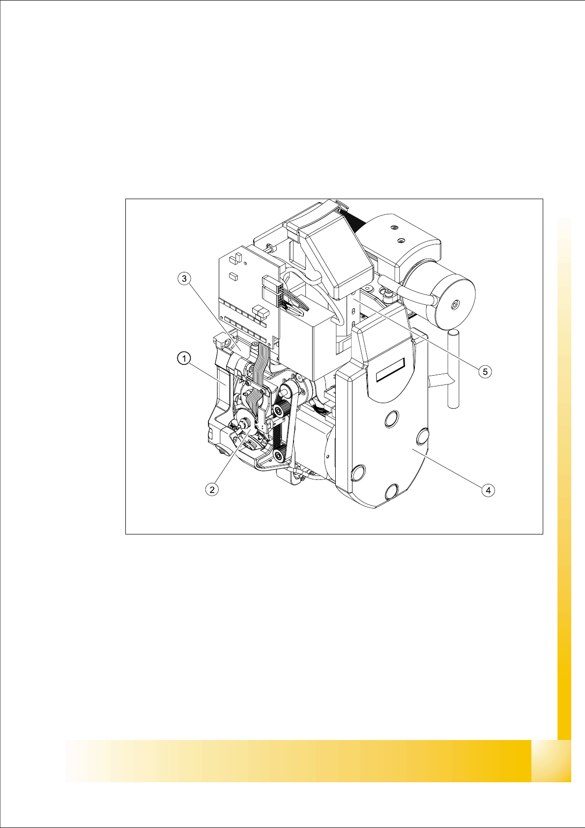
Fig. 6.1 - 1 12-segment DLM2 Collect&Place head - overview
Legend
(1) Back part, complete / DLM2) (2) Star, fitted with 12 sleeves
(3) Front part, complete / DLM2 (4) Cover intermediate distribution board, digital
(5) 24x24 component camera