SG_FSE_SiplaceHF_HF3_00193901-05_eng.pdf - 第357页
1 - 9 S tudent Guide SIPLACE HF/HF3 Edition 09/2005 7 TWIN-Head 9 7.6.3 Axis control TWIN- Head Z-axis The Z axis is d riven with a 3 phase AC linear mo tor with an intermediate circuit voltage of 60V . The control of th…
1 - 9
Student Guide SIPLACE HF/HF3
Edition 09/2005 7 TWIN-Head
9
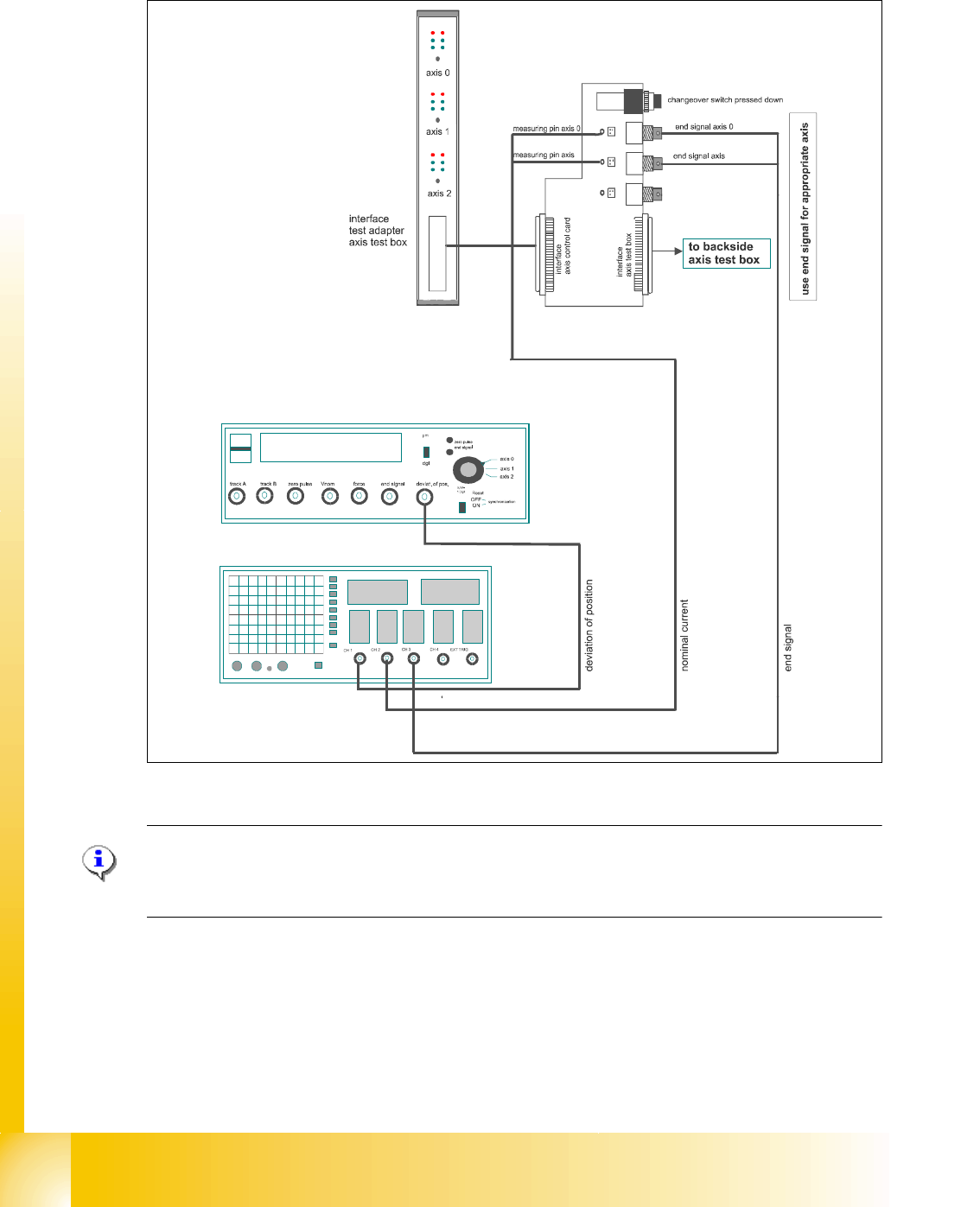
7.6.3 Axis control TWIN- Head Z-axis
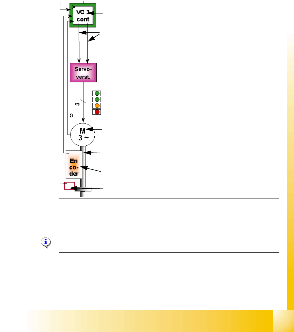
The Z axis is driven with a 3 phase AC linear motor with an intermediate circuit voltage of 60V.
The control of the axis occurred with two control signals of the VC3 (dephasing 120°) controller
I
nom "W" and I nom "U". The third phase is calculated at Servo amplifier.
Fig. 7.6 - 4 Axis control Z-axis TWIN- head
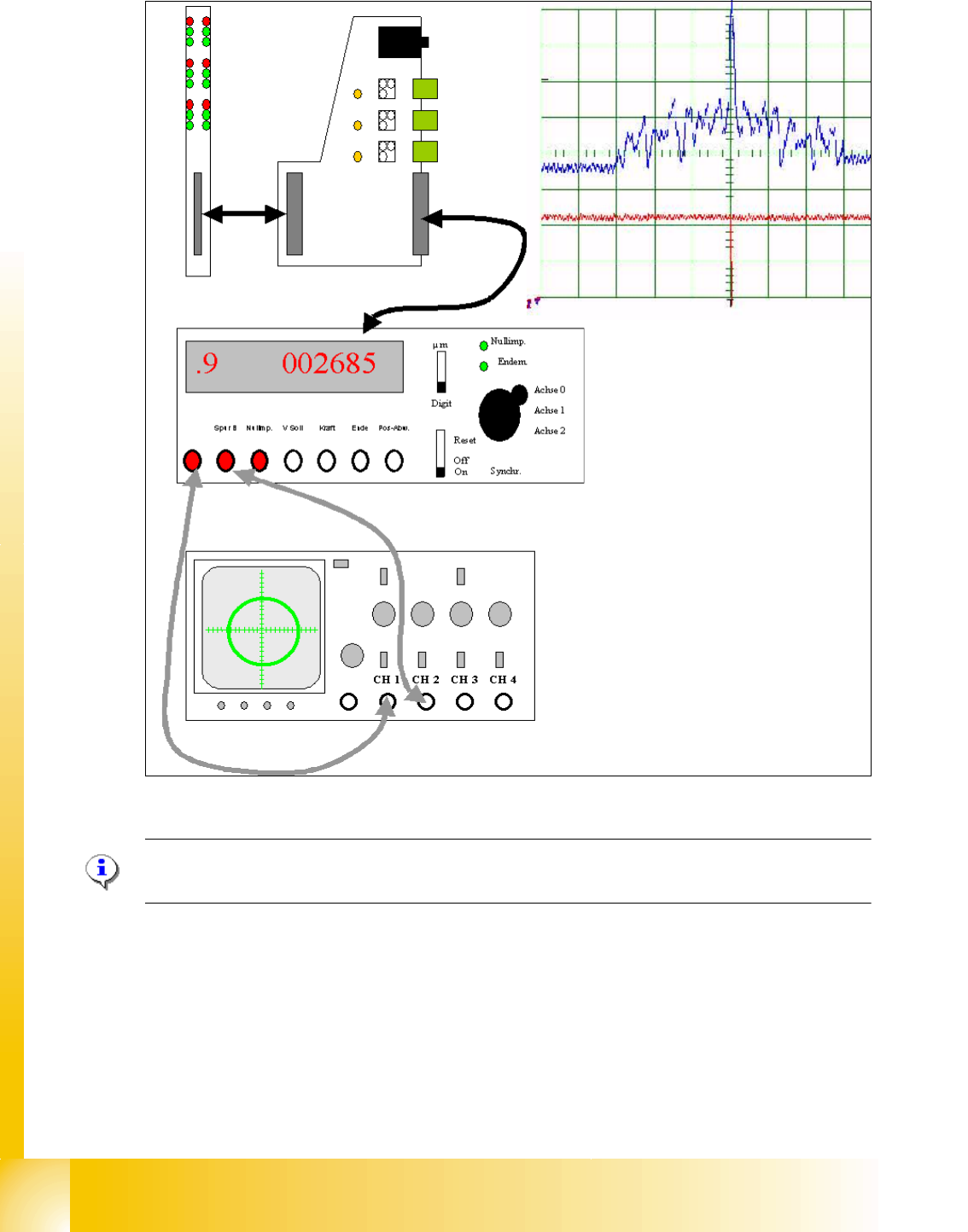
7.6.3.1 Check the dynamic of Z-axis
Please Note:
For check the dynamic please use the official Adjustment manual.
Axis board A363 with VC 3 Controller (VC = Velocity Commutation)
Control signals I
soll "W" and I soll "U"
Servo board control directly the linear motor, Intermediate (DC) voltage cir-
cuit is 250V.
LED‘s on Servo board:
– Power supply ON
– Servo enable, it the enable signal from the axis board.
–Display I
RMS limit shorter than 2,5 s.
– Error: Over voltage, -current, -temperature longer than 2,5 sec.
3 Phase AC linear motor with integreted temperatur sensor.
Between motor and incremental scale exist a fixed mechanically connec-
tion.The incremental encoder is fixed on the frame of the TWIN- head.
Incremental encoder: Transmitted the correct position to the axis board and
is the only feedback signal to control the motor (Track signals).
Force sensor