SG_FSE_SiplaceHF_HF3_00193901-05_eng.pdf - 第117页
1 - 3 S tudent Guide SIPLACE HF/HF3 Edition 09/2005 4 Servic es to the machine 3 4 Services to the machine 4.1 Overview the figure be low shows the p osition of th e units which create and distribute the supply voltages …

1 - 2
Student Guide SIPLACE HF/HF3
Contents Edition 09/2005
2
4.3.3.6 Safety valve X60. . . . . . . . . . . . . . . . . . . . . . . . . . . . . . . . . . . . . . . . . . . . . . . . . 42
4.3.3.7 Pneumatic loop Cooling Y - Linear motor for Placement area 1/2 . . . . . . . . . . . 43
4.3.3.8 Pneumatic loop Cooling X - Linear motor for Placement area 1. . . . . . . . . . . . . 44
4.3.4 Pneumatic Supply Tape Cutter . . . . . . . . . . . . . . . . . . . . . . . . . . . . . . . . . . . . . . . . . 44
4.3.5 Pneumatic Supply Docking Unit (Compnent-table 1-4). . . . . . . . . . . . . . . . . . . . . . . 45
4.3.6 Bulk Case System and Nozzle Changer . . . . . . . . . . . . . . . . . . . . . . . . . . . . . . . . . . 45
4.3.7 Pneumatic Supply Collect and Place Haed . . . . . . . . . . . . . . . . . . . . . . . . . . . . . . . . 46
4.3.8 Pneumatic Supply Twin Head:. . . . . . . . . . . . . . . . . . . . . . . . . . . . . . . . . . . . . . . . . . 47
4.3.8.1 Air distribution TWIN-head . . . . . . . . . . . . . . . . . . . . . . . . . . . . . . . . . . . . . . . . . 48
4.3.8.2 Z-axis safety process . . . . . . . . . . . . . . . . . . . . . . . . . . . . . . . . . . . . . . . . . . . . . 50
1 - 3
Student Guide SIPLACE HF/HF3
Edition 09/2005 4 Services to the machine
3
4 Services to the machine
4.1 Overview
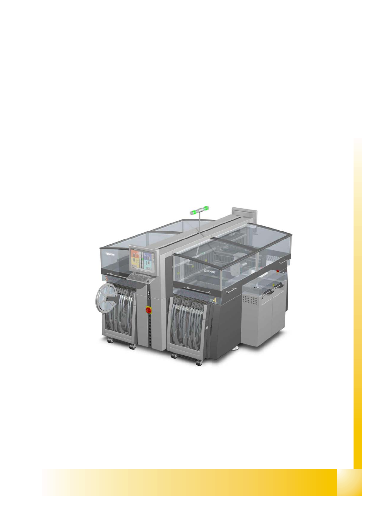
the figure below shows the position of the units which create and distribute the supply voltages
needed to operate the system
– power supply unit containing main distributor (pos. 1)
– section distributor section 2 (pos. 2)
– pneumatic unit (pos. 3)
– section distributor section 4 (pos. 4)
Fig. 4.1 - 1 HF/HF3 main units identical at original - and ’A’ version of HF-machine
P
o
w
e
r
s
u
p
p
l
y
Section 4
Section 2
P
n
eu
m
at
ic
U
n
it
3
1
4
2
1 - 4
Student Guide SIPLACE HF/HF3
4 Services to the machine Edition 09/2005
4
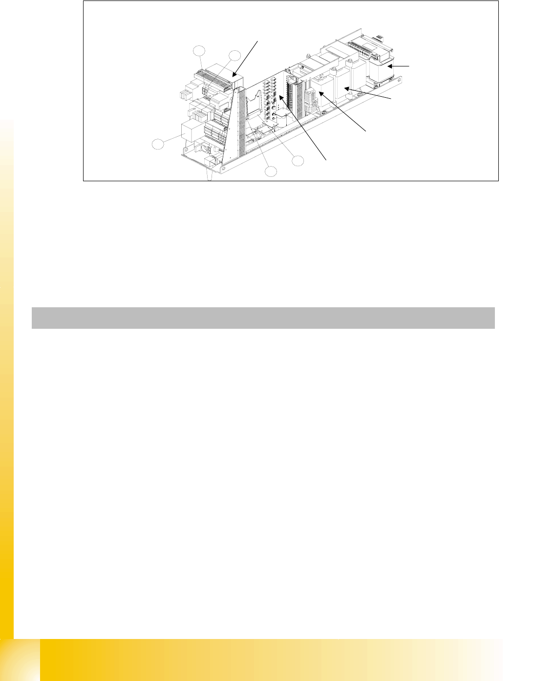
4.1.1 Overview power supply
Fig. 4.1 - 2 main power supply unit identical in original - and ’A’ version of the HF-Machine
Legend
(1) DC/DC Converter 24 V (4) Fuse F5 for star axis
(2) DC/DC Converter 5 V at HFand 5V/24V at HF3 (5) Fuse F11 for inrush current limiter
(3) Safety combination relay K6
1
2
3
4
5
main distributor main
power supply
Inrush current limiter:
a: transformer: EST
b: servo: Ess
transformer T2
transformer T1
T1
T2
Fuse F61 - fuse F142
Units Identification Contact Voltages
X100 main power supply L1, L2, L3 3 x 204 VAC / 3 x 380 VAC
3 x 400 VAC / 3 x 415 VAC
X102 service socket 115 VAC / 220 VAC / 230 VAC / 240 VAC
Q1 main switch 1, 3, 5 u.
2, 4, 6
3 x 204 VAC / 3 x 380 VAC
3 x 400 VAC / 3 x 415 VAC
Q2 motor circuit breaker 1, 3, 5 u.
2, 4, 6
3 x 204 VAC / 3 x 380 VAC
3 x 400 VAC / 3 x 415 VAC
K1 main contactor 1, 3, 5 u.
2, 4, 6
3 x 204 VAC / 3 x 380 VAC
3 x 400 VAC / 3 x 415 VAC
K2 contactor 1, 3, 5 u.
2, 4, 6
3 x 177 VAC
K3 contactor 1, 3, 5 u.
2, 4, 6
3 x 177 VAC
K4 contactor 1, 3, 5 u.
2, 4, 6
3 x 177 VAC