SG_FSE_SiplaceHF_HF3_00193901-05_eng.pdf - 第371页
1 - 3 S tudent Guide SIPLACE HF/HF3 Edition 09/2005 8 Co mponent handling 3 COT model for ’A ’-machine with One -Hand Operation 8 The docking unit is iden tical for both v ersions of the COT! the elec trical circuit is c…
1 - 2
Student Guide SIPLACE HF/HF3
8 Component handling Edition 09/2005
2
Technical Data component table: 8
8.1.1 Component changeover table (COT)
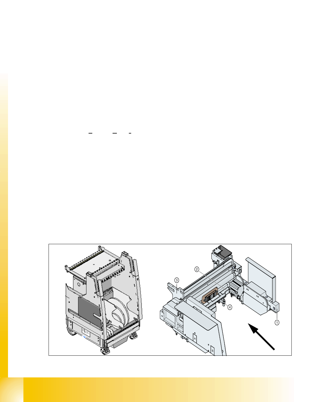
The component handling unit consist of the COT and the docking unit with tape cutter.
COT model 1 with Two -Hand -Operation 8
For the docking process, push the component changeover table into the docking unit as much as
possible. Mount COT by activating the two buttons (see Fig. 10.1 - 1) to the machine. Than the
feeder is lifted and pulled towards the machine by two pneumatic cylinders and cam disks.
For the undocking process, open the cover and press the button 1 (see Fig. 10.1 - 1). Than the
feeder table is pushed out and lowered. This happen by two pneumatic cylinders and the two
pneumatic cylinders operating the cam disks.
Electrical and pneumatical supply is automatically connected by a central ODU-connector in the
docking unit.
Fig. 8.1 - 2 COT -model 1 with the docking unit
Feeder capacity
180 tracks width 8mm (3x8mm S feeder)
120 tracks width 8mm (2x8mm S feeder)
Location
4 Component tables with the integrated tape waste container
15 tracks via 30mm for each component table or up to 2 matrix tray changer
undocking
with electric and pneumatic supply or completely manuell when machine is OFF
docking
only with electric and pneumatic supply
Feeder types
Tapes, Bulkcase, Linear magazin, Siplace S-Feeder(F4,F5,S-20,S-
23,S25HM,S27HM,HS50,HS50+,HS60), OEM Feeder, Surftape feeder (8, 12,
16, 24 mm), manual Trays
Interface to the machine
automatically connection if docking the COT
- connect to Power - connect to CAN Bus
- connect to Safety loop - connect to pneumatic air
- connect to the option Splice detection
Component table height
depend from the machine height: Freely adjustable on following SMEMA heights
830 mm ± 15 mm (Standard) 900 mm ± 15 mm (SMEMA)
930 mm ± 15 mm (SMEMA) 950 mm ± 15 mm (SMEMA)
1 - 3
Student Guide SIPLACE HF/HF3
Edition 09/2005 8 Component handling
3
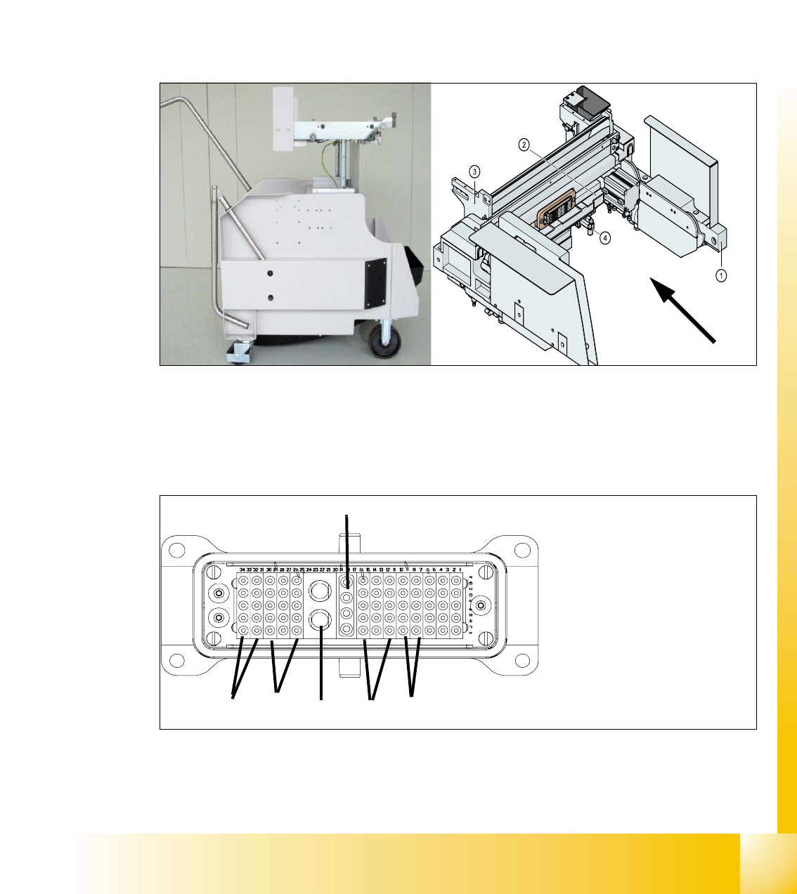
COT model for ’A’-machine with One -Hand Operation 8
The docking unit is identical for both v ersions of the COT! the electrical circuit is changed for one
hand operation.
For the docking process, push the component changeover table into the docking unit as much as
possible, the safety cover have to be be closed. Press button (3) (see Fig. 10.1 - 1) and the COT
is mounted to the machine like described before.
For the undocking process, open the safety cover at the respective area and press button 3 (see
Fig. 10.1 - 1). Now the COT move out like described before.
Fig. 8.1 - 3 COT -model 2 with the docking unit
Connection the COT to the machine 8
Fig. 8.1 - 4 ODU Connector for COT (first model)
1. Power
2. Safety loop
3. Signaling
4. Compressed air Bulk Case
5. Splice detection
6. CAN Bus
(4)
(5)
(2)
(1)
(3)
(6)
1 - 4
Student Guide SIPLACE HF/HF3
8 Component handling Edition 09/2005
4
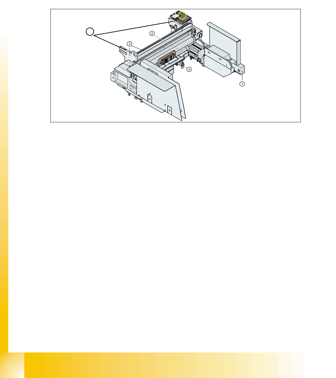
8.1.2 Pneumatic tape cutter and empty tape duct
The pneumatic tape cutter unit is fixed to the frame of the docking unit with 4 screws. It cuts plastic,
aluminum and paper tapes up to a maximum pocket depth of 25 mm. The waste tape fall via the
tape waste chute into the tape waste container below the component table. The empty tape duct
is constructed, that the cutting edges of the tape cutter is covered (Safety), the empty tape duct
has an integrated reject box and mounting suface for nozzle changers of 6 or12 nozzle C&P head
or Twin head.
Fig. 8.1 - 5 Complete docking unit
1. Frame docking unit 2. Pneumatic tape cutter
3. Empty tape duct 4. Electrically and pneumatically connector to the machine
5. Support for the nozzle changer (6) Component reject box for C&P-head
5
6