SG_FSE_SiplaceHF_HF3_00193901-05_eng.pdf - 第249页
1 - 49 S tudent Guide SIPLACE HF/HF3 Edition 09/2005 6 Colle ct &Place-Head / DLM2 49 6.4 Adjustment s 6.4.1 Description of th e switches and PCB boa rds on the C&P head 6.4.1.1 Head interface The same head inter…

1 - 48
Student Guide SIPLACE HF/HF3
6 Collect &Place-Head / DLM2 Edition 09/2005
48
6.3.37 Description air kiss control
Air kiss control at placement: 6
Value “0” mean the blast air valve don‘t switch on.
(1) Value “1-50” mean blast air valve is switched OFF when stepper motor valve drive start to
move.
(2) Value “51-150” mean blast air valve is switched OFF when stepper motor valve drive moved
for 90 degree.
(3) Value. “151-255 mean blast air valve is switched OFF when stepper motor valve drive moved
for 180 degree.
Or at light barrier top.
No value “----” (from converting 501/502 to 503 format) mean same mode than
(3) (existing
standard).
Air kiss control at return component! (not reject) 6
(4) Value and description like (1)
(5)
Value and description like (2)
(6)
Value. “151-255” mean blast air valve is switched OFF when stepper motor valve drive moved
for 180 degree.
Please Note
More Information about the air kiss control see chapter C&P head with (Flow chart).
1 - 49
Student Guide SIPLACE HF/HF3
Edition 09/2005 6 Collect &Place-Head / DLM2
49
6.4 Adjustments
6.4.1 Description of the switches and PCB boards on the C&P head
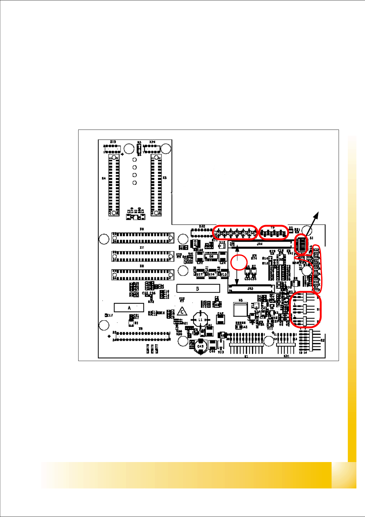
6.4.1.1 Head interface
The same head interface board will be use on Gantry 1 and Gantry 2 for the twin head and C&P
head.
Fig. 6.4 - 1 Headinterface
1. X11 Connector Temperature sensor X-Axis
2. X17 Connector BERO Travel range X-Axis
3. X16 Connector BERO Travel range X-Axis
4. X15 Connector for incremental encoder X-Axis
5. X24 Test connector digital track signals X-Axis
6. Connector for "16 bit Prozessor board"
LED 1-7 TP 1-8
LED 1-10
DIP Switch
1
2
3
4
5
6

1 - 50
Student Guide SIPLACE HF/HF3
6 Collect &Place-Head / DLM2 Edition 09/2005
50
Description LED‘S and DIP switches on the Headinterface: 6
LED 1-7 (functional check)
– SPI - Serial parallel interface (A/D or D/A converter in future)
– D-ON - Digital ON 5V DC/DC Converter
– H-OK - Head adapter board connected
– C-In - CAN Internal not used
–MRST -Main Reset
– F-UC - not used
– MP - Main Power fail, mean 5 V power supply being missing at the machine (e.g. CAN
Bus)
LED 1-10 (LED´s for voltages)
– Vcc - Power supply +5 V head interface
– N15V - Minus 15 Volt (from the Axis unit--> Error--> LED red)
– P3,3V - Not used
– P15V - Plus 15 Volt (from the Axis unit--> Error--> LED red)
– P24V - 24 Volt power supply (e.g.stepper motor)
– AV ER - Not used
–EN AN - Not used
– P5V - 5 Volt Power supply track signals X-Axis --> ON Power fail
– VccF - 5 Volt for digital
– TMP - Temperature monitoring X-Axis
Please Note:
The DIP Switch configuration for the gantry configuration is decribed in chapter gantry.