SG_FSE_SiplaceHF_HF3_00193901-05_eng.pdf - 第42页
1 - 16 S tudent Guide SIPLACE HF/HF3 2 Overview Edition 09/2005 16 2.2.5 Computer unit Fig. 2.2 - 7 Computer unit (1) Slide in rack; Computer unit (2) ICOS 1(lef t) Placement area 1 / ICOS 2 Place ment area 2 (3) Fan uni…
1 - 15
Student Guide SIPLACE HF/HF3
Edition 09/2005 2 Overview
15
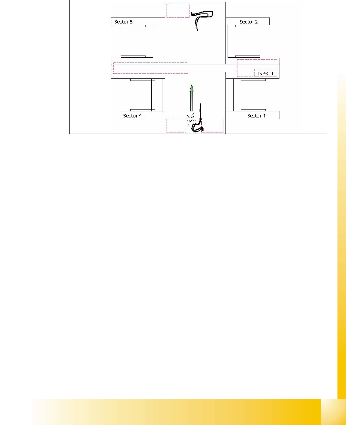
2.2.4 Sectors 1 - 4
Fig. 2.2 - 6 Overview Sector 1-4
Sector 1/3: 2
– Connector modules for safety loop and Start/Stop switch
– circuit for onehand operated comp.tables at location 1/3 respective sector 3 for location 3/4.
– Sector 1-> Hub for the Option Splicedetection
Sector 2 (Main Distributor): 2
– CAN I/O Module
– Vision illumination control board for Twin head IC-Camera or FC Camera (Option)
– DC/DC converter for Twin head IC-Camera (Flash signal)
– Main distributor (Connector moduls)
– Terminals X1qa (GND,+5V,+15V,-15V,+24V,.Start/Stop-signal, Covers, emergency stop sig-
nal,SW-enabling signal)
– Connector modules for safety loop and Start/Stop switch
Sector 4 (Sub Distributor): 2
– CAN I/O Modul
– Vision illumination control board for Twin head IC-Camera or FC Camera (Option)
– DC-distributer for Twin head IC-Camera (Flashsignal) in Placement area 1 if installed.
– Sub distributor (Connector moduls)
– Terminals X1ra (GND,+5V,+15V,-15V,+24V,Start/Stop-signal, Covers, E-stop signal,...)
– Connector modules for safety loop and Start/Stop switch
Axis unit PA 2
Axis unit PA 1 HF3
1 - 16
Student Guide SIPLACE HF/HF3
2 Overview Edition 09/2005
16
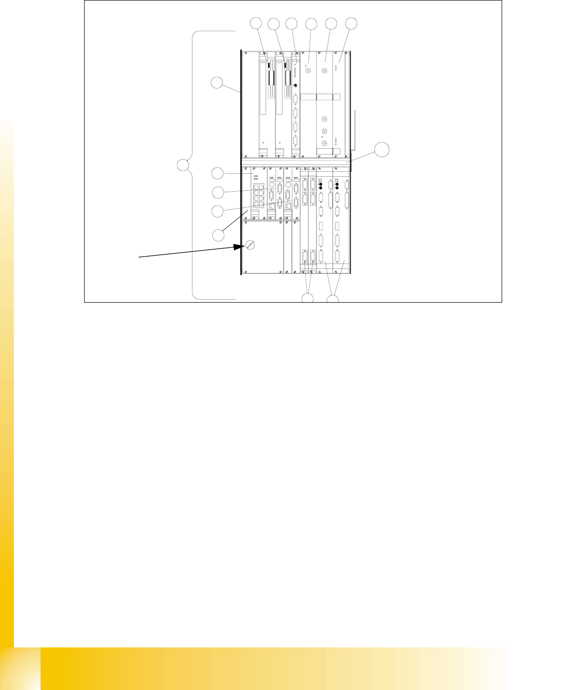
2.2.5 Computer unit
Fig. 2.2 - 7 Computer unit
(1) Slide in rack; Computer unit
(2) ICOS 1(left) Placement area 1 / ICOS 2 Placement area 2
(3) Fan unit
(4) Slot for coplanarity Control unit
(5) CPU unit machine controller (MC)
(6) CPU unit station computer (SC)
(7) Harddisk/Floppydisk/CD-ROM SC (left) Harddisk/Floppydisk/CD-ROM MC(right)
(8) Power supply DC/DC Converter +/-12V (+/-15V not used)
(9) Power supply DC/DC Converter 3,3V (CPU‘s)
(10) Power supply DC/DC Converter 52V / +5V 60A
(11) Dual LAN unit
(12) Video multiplexer
(13) COM unit 1Mbit/s(left) CAN BUS / COM unit (right) (not used on HF 504) used on HF 505
COM unit 1Mbit/s(left) CAN BUS for BB1 / COM unit 1Mbit/s(right) for BB2 on the HF3
(14) Space for additional COM interface (serial Port) for the option Traceability
3,6V
Batterie
Reset
Abort
X9pu X5pu X8puX7pu X6pu
X3pu X4pu
HS3LVGAAUXKamera 1/3Kamera 2/4
S-COM 2 S-COM 1
S-COM 1S-COM 2
Kamera 2/4 Kamera 1/3
AUX VGA HS3L
X4ptX3pt
X6ptX7pt
X8ptX5ptX9pt
Abort
Reset
X7po
CAN-Bus
X6po
CAN-Bus
X2po
S-COM 1
S-COM 1
X2pn
CAN-Bus
X6pn
CAN-Bus
X7pn
L1
L2
H1
H2
LAN1 LAN2 HUB 6 HUB 5
HUB1HUB2HUB 3HUB4
H3
H4
H5
H6
Activity
COM-ACOM- B
VGALAN
X6pa
X8pa X7pa
X5
L3
L4
L5
L6
KEYB.
USB
RUN
WD
L1
L2
USB
USB
L2
L1
WD
RUN
USB
KEYB.
L6
L5
L4
L3
X5
X7pcX8pc
X6pc
LAN
VGA
COM-B COM-A
Harddisk
Floppy
CD
CD
Floppy
Harddisk
ICOS 2ICOS 1GEMMC
X4pvX3pvX2pvX1pv
3,3V + 52V
+ 5V
+12V
-12V
+15V
-15V
GND
7
7
12
9
10
8
18
4
11
6
5
13
2
1
3
14
Battery
3,6V
1 - 17
Student Guide SIPLACE HF/HF3
Edition 09/2005 2 Overview
17
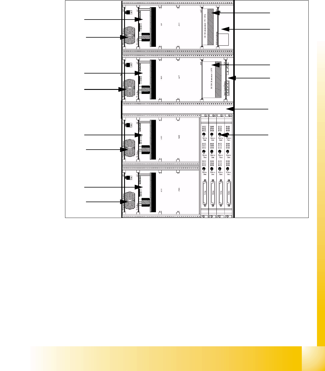
2.2.6 Axis Unit HF machine
The axis unit contains the servo boards, axis boards, power supplys (+/-15V,+5V), ballast circuit
and anti-crash board. The flexible axis (Servo) unit will be equipt with servo boards according the
machine configuration.
Fig. 2.2 - 8 Axis unit HF
(1) Power supply +/-15V, +5V
(2) Ballast circuit board
(3) Power supply +/-15V
(4) Anti crash board
(5) Fan unit
(6) Axis board A363
(7) Servo board X-Axis Placement area 1/2
(8) Servo board Y-Axis Placement area 1/2
(9)
Brake board for each X and Y Axis
A9 -> A16
Servo boards according Machine configuration
X
1
Z
RV
X
2
Z
T1
Y
1
DP
RV
Y
2
DP
T1
S
1
F
RV
Z
T2
DP
T2
A9
S
RV
(Z
T2
)
BB1
A10
Z
T2
BB2
A11
Z
RV
(Z
T1
)
BB1
A12
Z
T1
BB2
A13
Fre e
(DP
T2
)
BB1
A15
DP
Rv
(DP
T1
)
BB1
A16
DP
T1
BB2
A14
DP
T2
BB2
1
2
3
4
5
6
7
9
8
9
7
9
8
9
Placement area 1
Gantry 1
Placement area 2
Gantry 3