SG_FSE_SiplaceHF_HF3_00193901-05_eng.pdf - 第351页
1 - 3 S tudent Guide SIPLACE HF/HF3 Edition 09/2005 7 TWIN-Head 3 Legend ➠ Align the nozzle changer so that the markin g hole (item 1) is on the lef t, as viewed by the op- erator at component t able side. 7.5.2.3 Descri…
1 - 2
Student Guide SIPLACE HF/HF3
7 TWIN-Head Edition 09/2005
2
7.5.2 Position and assembly the nozzle changer
7.5.2.1 Position
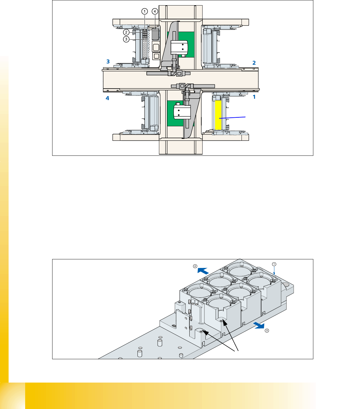
Fig. 7.5 - 2 Position nozzle changer "Standard configuration" here are on location 3 HF machine
Legend (The blue numbers show the feeder areas.)
7.5.2.2 Assembly nozzle changer magazine
The nozzle changer together with the empty tape duct is fixed on the component docking unit. The
magazines are seated on a common support. They are centered with two parallel pins and fixed
in place with two countersunk screws.
Fig. 7.5 - 3 Assembly magazine
(1) Nozzle changer no. garage 1 (2) Standard magazine set up
(3) Magazine for special nozzles or grippers (4) Component reject bin
Option TWIN on G1
nozzle changer space
(4)
1 - 3
Student Guide SIPLACE HF/HF3
Edition 09/2005 7 TWIN-Head
3
Legend
➠ Align the nozzle changer so that the marking hole (item 1) is on the left, as viewed by the op-
erator at component table side.
7.5.2.3 Description of the functions
The magazine for standard nozzles has 1 positioning fiducial for position detection, while the mag-
azine for special nozzles/grippers has two positioning fiducials. The nozzles are fixed by balls in
the holder. They are then either clamped for return or released for pick up, depending on the di-
rection of rotation of the DP axis.
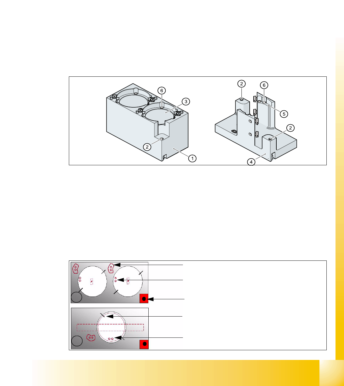
Fig. 7.5 - 4 Magazine for standard- and special nozzles
Position of the nozzle in the magazines 7
(1) Fiducial for optical X/Y position recognition
of the magazine carrier.
(2) Arrow pointing to component table
(3) Arrow pointing toward the PCB conveyor (4) Fiducial for optical X/Y position recognition
of the magazines.
(1) Standard magazine (2) Positioning fiducia
(3) Nozzle holder (4) Magazine for special nozzles
(5) Nozzle holder (6) Balls for lifting the nozzles
1
2
- Description of the index pins for the right
position of the nozzle in the magazine.
- Position of the nozzle with the holes for the
index pins. (pick up angle 184 degree)
- Fiducial for calibration, serves for the position
determination of the magazine.
- centering pins for the nozzles
- The magazines for the special nozzles are
turned 90° degree pick up angle 275°.