SG_FSE_SiplaceHF_HF3_00193901-05_eng.pdf - 第204页
1 - 4 S tudent Guide SIPLACE HF/HF3 6 Collect &Place-He ad / DLM2 Edition 09/2005 4 6.1.2 Step s when pickin g up and placing components – A PCB moves into the placement area of the PCB conveyor . – After the fidu ci…
1 - 3
Student Guide SIPLACE HF/HF3
Edition 09/2005 6 Collect &Place-Head / DLM2
3
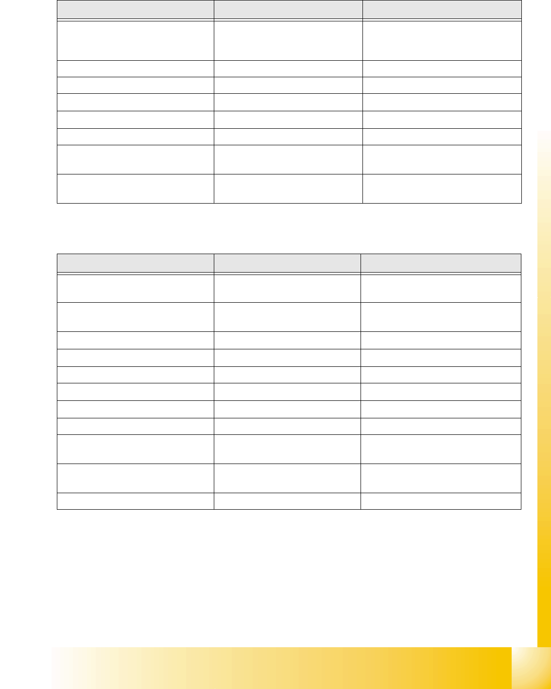
6.1.1.1 Technical Data: 6 Segment / 12 Segment C&P heads.
6.1.1.2 Camera modularity at the 6segment C&P head for example.
Description 12 segment DLM 2 6 segment DLM 2
Component size
1mm x 0,5mm (0402)/0,5mm x
0,25mm (0201) up to
18,7 mm x 18,7 mm
1,5mm x 0,75 mm (0603) up to
32 mm x 32 mm
Component height 6,0 mm 8,5 mm
Component weight 2,0 g 5,0 g
Placement Accuracy
+/- 60µm at 4 (Sigma) +/- 60µm at 4 (Sigma)
Angle Accuracy
+/- 0,7° at 4 (Sigma) +/- 0,3° at 4 (Sigma)
Placement force 2,4 - 5,0 N 2,4 - 5,0 N
Nozzle types
901, 904, 905; 911-919; 920-
925; 931-937
901, 904, 905; 911-919; 920-925;
931-937 817, 820, 821
Nozzle changer
set up for each magazine or set
up for each garage set up for each garage
Table 6.1 - 1 Technical data 6 / 12 C&P heads
Description 6 segment DLM 2 6 segment DLM 2with DCA
Component size
1,5mm x 0,75 mm (0603) up to
32 mm x 32 mm
0,5mm x 0,25 mm (0201) up to
15 mm x 15 mm
Component dimension: FlipChip /
Bare Die --
1mm x 1 mm up to
15 mm x 15 mm
Component height: FlipChip / Bare Die
0,15 mm up to 1 mm
Component height
8,5 mm
8,5 mm
Component weight 5,0 g 5,0 g
Placement accuracy
+/- 60µm at 4 (Sigma) +/- 55µm at 4 (Sigma)
Angle accuracy
+/- 0,4° at 4 (Sigma) +/- 0,4° at 4 (Sigma)
Placement force 2,4 - 5,0 N 2,4 - 5,0 N
Nozzle types
901, 904, 905; 911-919; 920-
925; 931-937 817, 820, 821
All 9xx nozzles & FlipChip/Bare Die
951, 952, 953, 954, 955, 956
Nozzlechanger
set up for each garage
only 9xx magazine.
set up for each garage
Table 6.1 - 2 Technical data Component camras
1 - 4
Student Guide SIPLACE HF/HF3
6 Collect &Place-Head / DLM2 Edition 09/2005
4
6.1.2 Steps when picking up and placing components
– A PCB moves into the placement area of the PCB conveyor.
– After the fiducial measurement with both gantries for each placement area (with SW505), the
C&P head picks up components from the feeder moduls.
– The components are measured below the component camera and turned in the Dp station into
the correct angle position.
– In the star station 1 the component will be place.
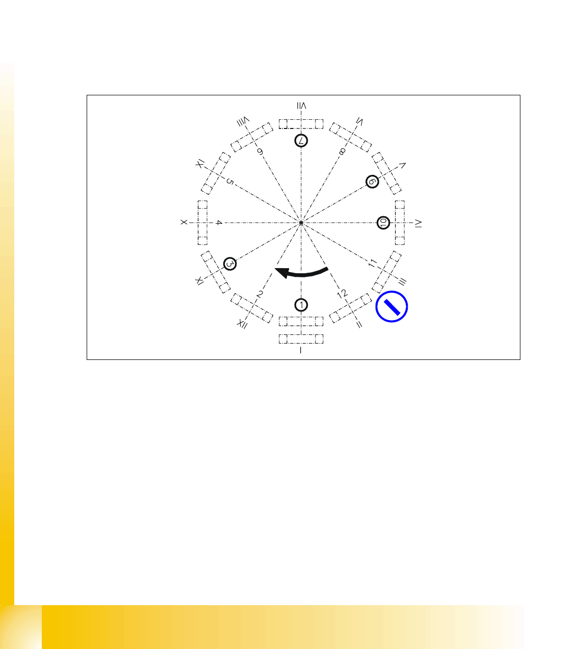
6.1.3 Position and function of the individual star stations
Fig. 6.1 - 2 Overview of the functions of star stations 1 - 12 I-XII segment numbers
I-XIISegment numbering
Star station 1: pick up, place and reject component 6
Star station 2: no function 6
Star station 3: no function (at HF/HF3 machine) 6
Star station 4, 5 and 6: no function 6
Star station 7: optically center component 6
Star station 8: no function 6
Star station 9: rotate component 6
Star station 10: position for removing and inserting sleeves 6
Star stations 11 and 12: no function (optionally Component sensor between star station 11 & 12)6
optionally:
Component sensor

1 - 5
Student Guide SIPLACE HF/HF3
Edition 09/2005 6 Collect &Place-Head / DLM2
5
Star station 1 6
Pick-up cycle
The nozzle is lowered onto the component. Once the valve positioning unit has opened the vac-
uum circuit to the nozzle, the nozzle draws up the component and removes it from the feeder mod-
ule.
Placement cycle
The nozzle, together with the component, is lowered onto the PCB that has been moved into
place. The valve positioning unit closes the vacuum channel to the nozzle. A short burst of com-
pressed air detaches the component from the nozzle and places it on the PCB.
Reject cycle
After the gantry reach the X- and Y-reject position the valve positioning unit closes the vacuum
channel to the nozzle. Defective components are detached from the nozzle with a short burst of
compressed air and are discarded.
Star station 7 6
The component is optically centered. 6
Star station 9 6
Pick-up cycle 6
The nozzle is rotated to the pick-up position. 6
Placement cycle
The component is rotated to the placement position (angle of rotation).
Star station 10 6
The SW move nozzles and sleeves to here for checking. 6
between Star station 11&12 6
Option on 12 nozzle head:
The component height is optically checked before placement.
6