SG_FSE_SiplaceHF_HF3_00193901-05_eng.pdf - 第352页
1 - 4 S tudent Guide SIPLACE HF/HF3 7 TWIN-Head Edition 09/2005 4
1 - 3
Student Guide SIPLACE HF/HF3
Edition 09/2005 7 TWIN-Head
3
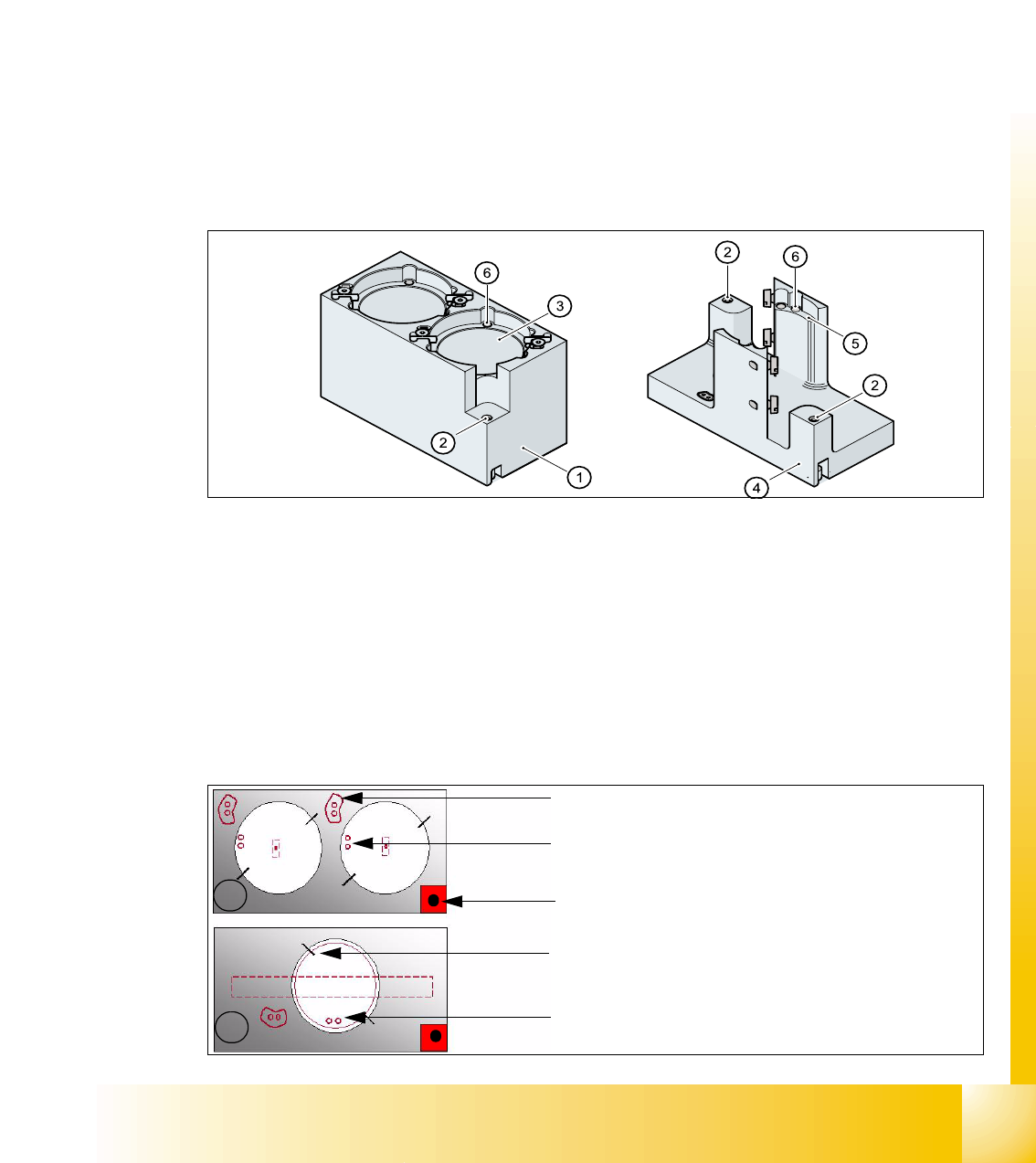
Legend
➠ Align the nozzle changer so that the marking hole (item 1) is on the left, as viewed by the op-
erator at component table side.
7.5.2.3 Description of the functions
The magazine for standard nozzles has 1 positioning fiducial for position detection, while the mag-
azine for special nozzles/grippers has two positioning fiducials. The nozzles are fixed by balls in
the holder. They are then either clamped for return or released for pick up, depending on the di-
rection of rotation of the DP axis.
Fig. 7.5 - 4 Magazine for standard- and special nozzles
Position of the nozzle in the magazines 7
(1) Fiducial for optical X/Y position recognition
of the magazine carrier.
(2) Arrow pointing to component table
(3) Arrow pointing toward the PCB conveyor (4) Fiducial for optical X/Y position recognition
of the magazines.
(1) Standard magazine (2) Positioning fiducia
(3) Nozzle holder (4) Magazine for special nozzles
(5) Nozzle holder (6) Balls for lifting the nozzles
1
2
- Description of the index pins for the right
position of the nozzle in the magazine.
- Position of the nozzle with the holes for the
index pins. (pick up angle 184 degree)
- Fiducial for calibration, serves for the position
determination of the magazine.
- centering pins for the nozzles
- The magazines for the special nozzles are
turned 90° degree pick up angle 275°.

1 - 5
Student Guide SIPLACE HF/HF3
Edition 09/2005 7 TWIN-Head
5
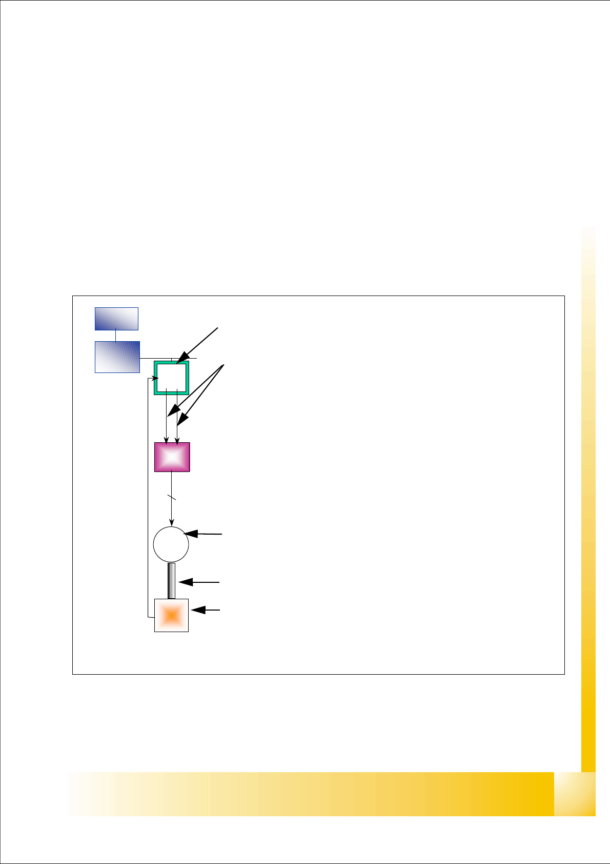
7.6 Axis control
7.6.1 Overview Axis control Z- and D-Axis
The closed-loop control system for control of the head axes consists of the following parts.
– Axis controller with VC 3 Controller
– Servo card (SDS)
– Motor
– Measuring system (Incremental- scale and -encoder)
Between the head axes, some differences which will be explain later in this chapter.
Fig. 7.6 - 1 Example: Axis control D-axis
MC
COM
board
VC 3
cont
Servo
ampli.
M
2 ~
Enco-
der
2
Axis card A363 with VC 3 Controller (VC = Velocity Commutation)
Control signals I
nom "W" and I nom "U"
LED‘s on the Servo amplifier:
– Power supply ON
– Servo enable, if the the enable signal from the axis board available.
– Display RMS current limiter shorter than 2,5 s.
– Error: Overvoltage, -current, -temperature or Nominal current-overstep-
ping longer than 2,5 sec.
Servo board control directly the motor.
2 Phase AC motor for D Axis.
3 phase AC linear motor for Z-Axis
Between the motor and the incremental encoder exist a fixed mechanical
combination.
Incremental encoder: trace the exact position of the axis via track signal.