SG_FSE_SiplaceHF_HF3_00193901-05_eng.pdf - 第172页
1 - 6 S tudent Guide SIPLACE HF/HF3 5 Gantry Edition 09/2005 6 5.2.2 X and Y commut a tion position search A commutation position search for the 3 phases AC-drives on the gantry start s right after the head axis referenc…
1 - 5
Student Guide SIPLACE HF/HF3
Edition 09/2005 5 Gantry
5
5.2 Reference run Gantry
5.2.1 Sequence reference run at X- and Y-axis
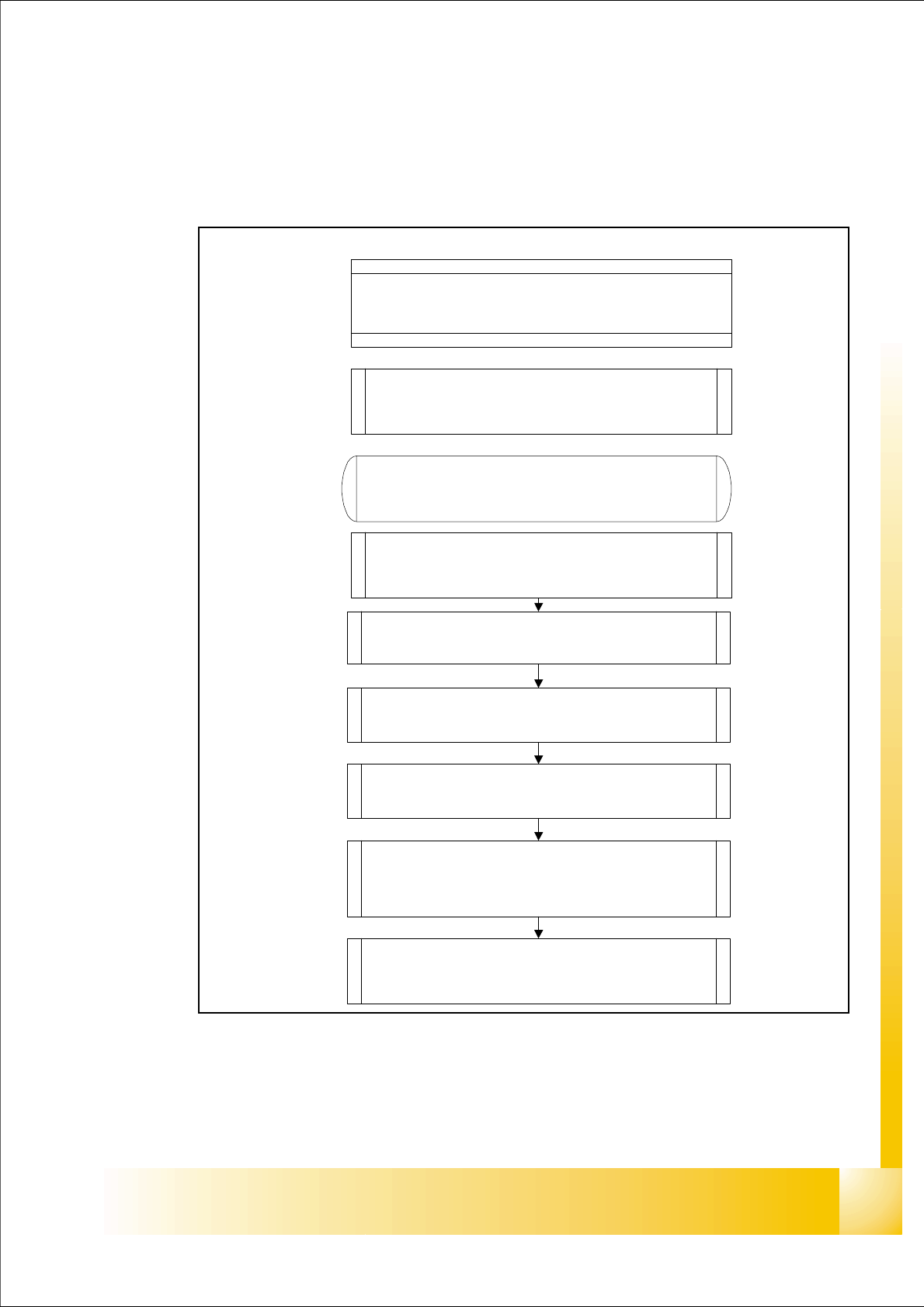
Fig. 5.2 - 1 Sequence Reference run X_Y
– Both axes are started at the same time.
Axes move to reference position
switch
Slope 1 to 0
change moving direction of axis
End signal for refence run is start
condition for the next step
Slope 0 to 1
start search for zero pulse
Zeropoint correction is loaded to
the axis controller when zero pulse
is recognized
Start X-Y- reference run
Preconditions: Reference Run
on Star-, Z- and DP- Axes is done
X - / Y -Axes Reference Run
Search the commutation position
of the linear motors
1 - 6
Student Guide SIPLACE HF/HF3
5 Gantry Edition 09/2005
6
5.2.2 X and Y commutation position search
A commutation position search for the 3 phases AC-drives on the gantry starts right after the
head axis reference run is succesfully finished.
A 3 phase motor move on and on when the current is switched from 1 phase to the next one, at
the correct time and in the correct sequence.
First one of the phases is connect to the power supply. With the incremental encoder the move-
ment is measured. Than the current is switched to the next phase and this movement is measured
too. The machine repeat this to control the measurement values.
This axis mode of commutation position search for the digital axis controller seams like a ”uncon-
trolled” shaking.
5.2.3 Reference run of X- and Y- axes
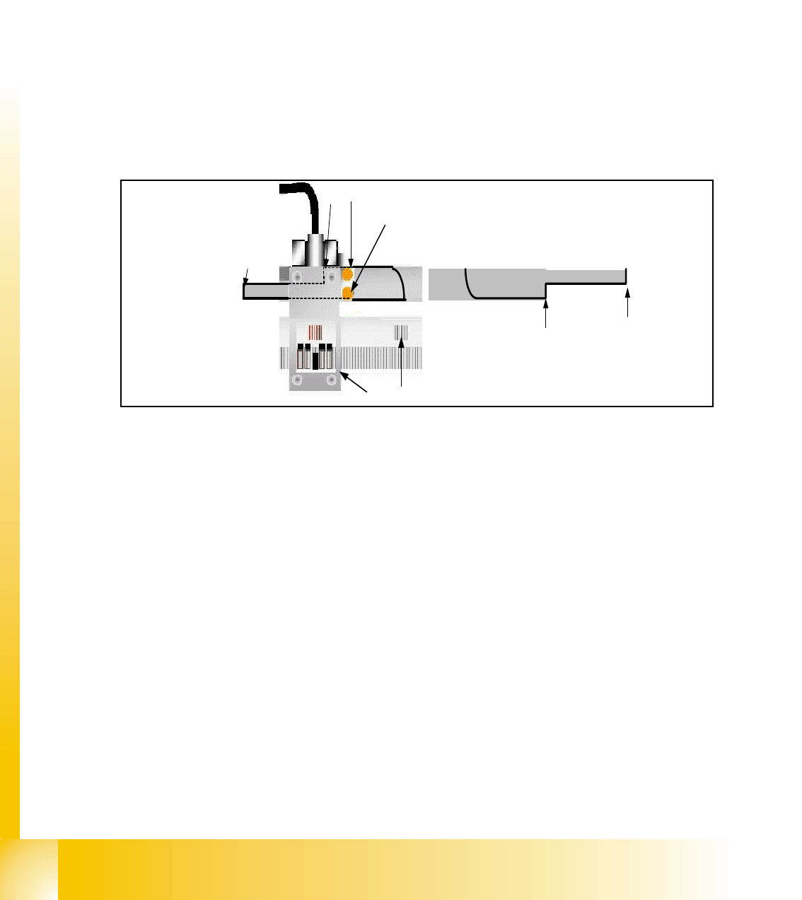
Fig. 5.2 - 2 Metal plate for switching position the BERO
1. Metal plate integrated into the machine frame
2. & 2b Switching position for HW-limit switch (Travel range)
3. Switching position for reference BERO / 3b start speed controled mode (near axis endstop)
4. BERO for limit switch (left side)
5. BERO for reference
6. First zero puls on the incremental scale
7. Incremental encoder
– The reference run is done with a defined travel range BERO and the incremental encoder.
– First the gantry axes move to the reference Bero (
4).
– If the switching position(
3) is detected the direction of movement is reversed and the Zero
pulse signal (
6) search starts.
– When the Zero pulse is detected the zero point correction is loaded to the axis controller. Ref-
erence run gantry axes is completed.
1
2b
3b
6
5
4
7
3
2