SG_FSE_SiplaceHF_HF3_00193901-05_eng.pdf - 第86页
1 - 16 S tudent Guide SIPLACE HF/HF3 3 Communication and Control Edition 09/2005 16 3.3.4 CAN Bus Concept on HF machine from MA. No. xx The placement machine SIPLACE HF uses a b us syst em with 1 Mb it/s transm ission ra…
1 - 15
Student Guide SIPLACE HF/HF3
Edition 09/2005 3 Communication and Control
15
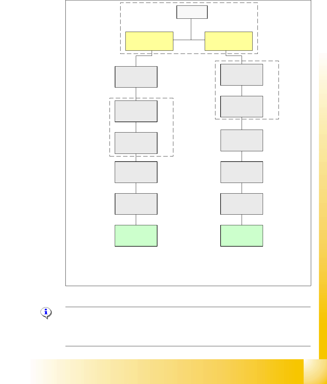
3.3.3 CAN Bus Concept on HF machine(up to MA.No. xx)
The placement machine SIPLACE HF uses a bus system with 1 Mbit/s transmission rate.The
CAN: Bus system begin at the Communication board and is split in 2 path. Every path is termi-
nated by a 120 ohm terminator on the CAN Bus board at the individual placement head.
Fig. 3.3 - 11 CAN Bus overall overview (new circuit diagrams)
Please Note: At SC/MC 505 update the gantry2 name change to gantry 3!!
The CAN- Wiring is changed that the cable went from COT3 to Gantry 3 and from Transport con-
trol to Gantry 1!! The CAN-Bus system is splited to 2 CAN-systems mean the second connector
at COMboard 1 is connected to COM 2!!
SMP BUS
MC
MC
Trailing cable-
Interface
Gantry 1
Trailing cable-
Interface
Gantry 2 *
CAN Bus cable 2
COT 3
Tape cutter
CAN Bus cable 1
Computer Unit
* SW Update 504 --> 505 Gantry 2 will be changed to gantry 3
old cable loop!
new circuit diagram!
Transport
Control
unit
COT 1
Tape cutter
Axis unit
PA 2
Vision
Section 2
CAN I/O
Main Module
Main Distributer Sektor 4
Control unit
Section 2
CAN E/A
Modul
Sektor 4
CAN E/A
Modul
Sektor 4
CAN E/A
Modul
Sektor 4
CAN I/O
SUB Module
Section 4
Vision
Control unit
SUB Distributor Section 4
Section 4
COT 2 / MTC
Tape cutter
COT 4 / MTC
Tape cutter
COM Unit
(left)
COM Unit
(right)
1 - 16
Student Guide SIPLACE HF/HF3
3 Communication and Control Edition 09/2005
16
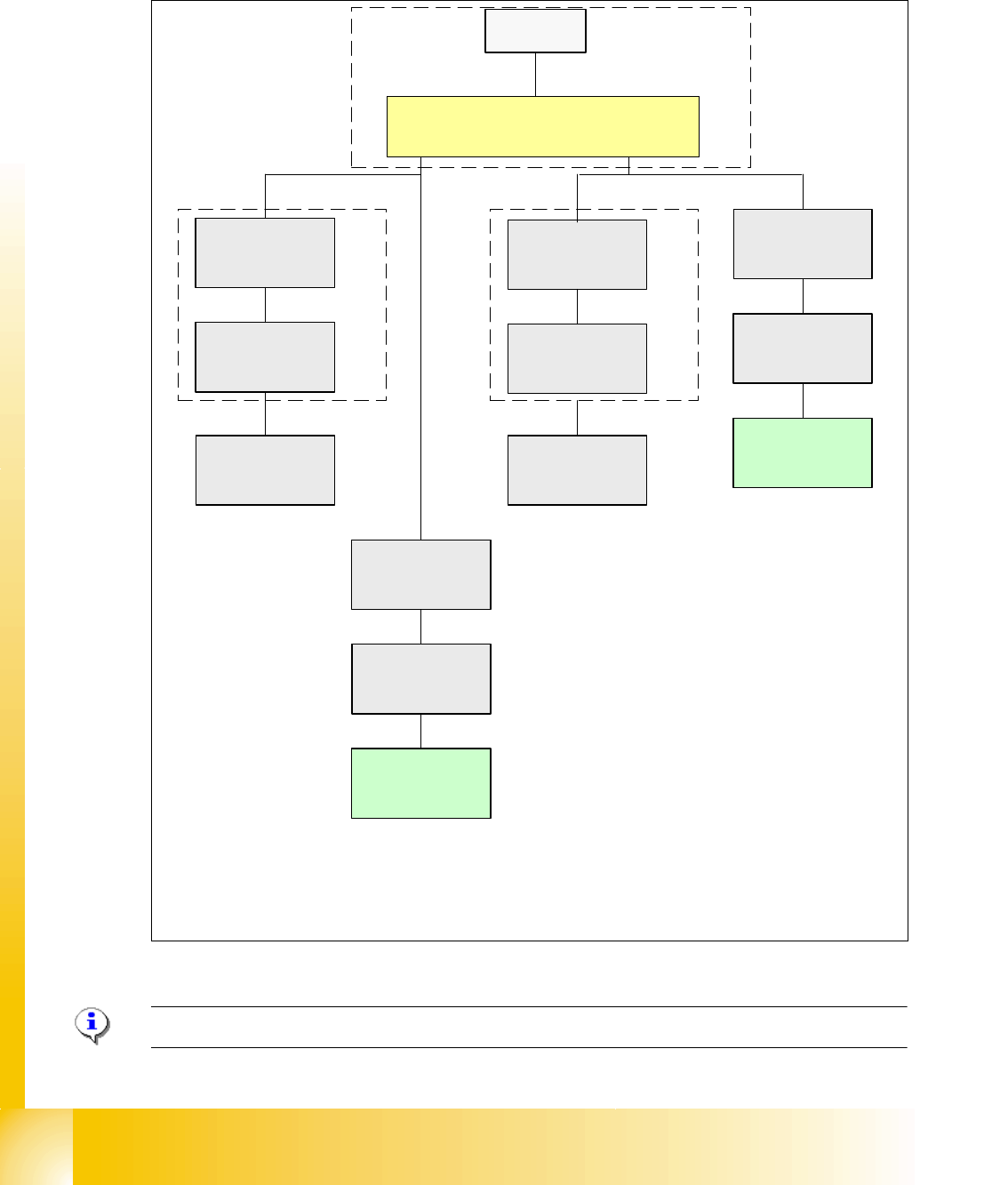
3.3.4 CAN Bus Concept on HF machine from MA. No. xx
The placement machine SIPLACE HF uses a bus system with 1 Mbit/s transmission rate.The CAN
Bus system begin at the Communication board and is split in 2 path. Every path is terminated by
a 120 ohm terminator on the CAN Bus board at the individual placement head.
Fig. 3.3 - 12 CAN Bus overall overview (new circuit diagrams)
Please Note: At SC/MC 505 update the gantry2 name change to gantry 3!!
SMP BUS
COM Unit
MC
MC
CAN Bus cable 1
Computer Unit
* SW Update 504 --> 505 Gantry 2 will be changed to gantry 3
new cable loop!
new circuit diagram!
Trailing cable-
Interface
Gantry 1
Transport
COT 1
Tape cutter
Control unit
CAN Bus cable 2
CAN E/A
Modul
Sektor 4
CAN E/A
Modul
Sektor 4
CAN E/A
Modul
Sektor 4
CAN I/O
SUB Module
Section 4
Vision
Control unit
SUB Distributor Section 4
Section 4
COT 4 / MTC
Tape cutter
Vision
Section 2
CAN I/O
Main Module
Section 2
Main Distributor Section 4
Control unit
COT 2 / MTC
Tape cutter
Axis unit
PA 2
COT 3
Tape cutter
Trailing cable-
Interface
Gantry 2*
1 - 17
Student Guide SIPLACE HF/HF3
Edition 09/2005 3 Communication and Control
17
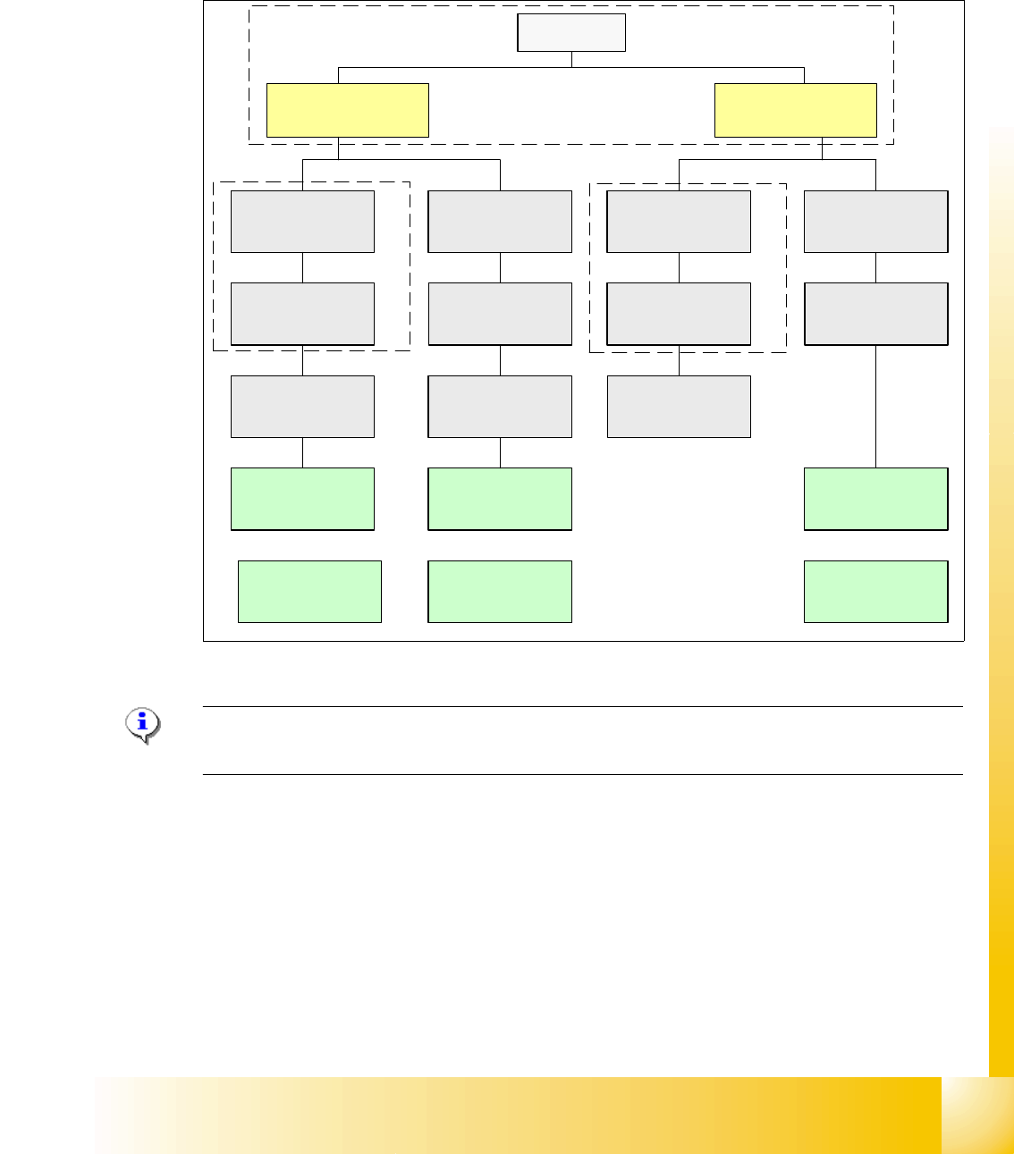
3.3.5 CAN Bus Concept on HF3 machine
The placement machine SIPLACE HF3 uses a bus system with 1 Mbit/s transmission rate.The
CAN: Bus system begin at the Communication board and is split in 2 path. Every path is termi-
nated by a 120 ohm terminator on the CAN Bus board at the individual placement head.
Fig. 3.3 - 13 CAN Bus overall overview HF3
Please Note: CAN: Bus Cable with "One wire Bus". The connector from the CAN: Bus cable,
that‘s connected on the COM Board, the wire on PIN 8/9 must not connected.
For datailed Connectors at the CAN-Bus system see actual circuit diagrams.
SMP BUS
COM Unit
(Left)
MC
MC
Axis unit
BB 1
Trailing cable-
Interface
Gantry 1
CAN Bus cable
COT 3
Tape cutter
Computer Unit
Transport
Control unit
COT 2 / MTC
Tape cutter
CAN E/A
Modul
Sektor 4
CAN E/A
Modul
Sektor 4
CAN E/A
Modul
Sektor 4
CAN I/O
SUB Module
Section 4
Vision
Control unit
COT 1
Tape cutter
COT 4
Tape cutter
SUB Distributer Section 4
Vision
Section 2
CAN I/O
Main Module
Sektor 2
Main Distributer Section 4
COM Unit
(Right)
Axis unit
BB 2
Section 4
Control unit
Trailing cable-
Interface
Gantry 3
Trailing cable-
Interface
Gantry 4
Head-Interface/
Visionboard
Gantry 4
Head-Interface/
Visionboard
Gantry 1
Head-Interface/
Visionboard
Gantry 3