SG_FSE_SiplaceHF_HF3_00193901-05_eng.pdf - 第451页
1 - 23 S tudent Guide SIPLACE HF/HF3 Edition 09/2005 10 Sitest 23 ➠ Then the gantry axes move the camera up to the star t position. This is centered according to the synthetic picture of the bright cross structure at thi…
1 - 22
Student Guide SIPLACE HF/HF3
10 Sitest Edition 09/2005
22
10.2.5 PCB mapping
With the PCB mapping the linearity of the X- and Y-guidance for PCB-camera movement is mea-
sured in the placement area.
The PCB-camera center the cross fiducials on a high precise glass plate. This glass plate is cali-
brated with a measurement machine and this data´s are considered in the measurement se-
quence.
Preperation mapping: 10
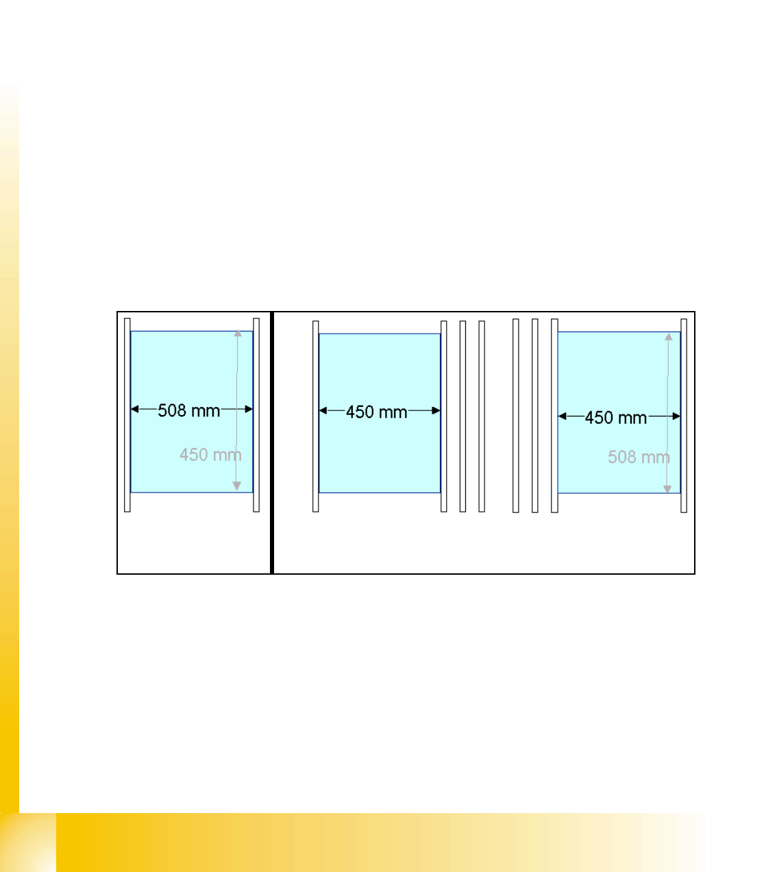
➠ At the single conveyor the SITEST move the transport rails to 508mm wide the mapping plate
is 90 degree turned.
➠ At dual conveyor the SITEST SW move all the transport rails depend of the track which is se-
lected the conveyor for mapping to 450 mm wide the other track to 0mm. This allow to used
the Dual conveyor as a single conveyor. The Mapping must be carried out for the maximum
conveyor width.
➠ To prepare the PCB and RV Mapping the SITEST SW move automatically the Transport rails
that the mapping plate fit to the the referring track.
➠ The C&P Heads have to have 956 nozzles the TWIN have to have 517 nozzles for mapping.
➠ The calibration tools are in the calibration pocket.
Fig. 10.2 - 10 Position mapping plate and conveyor rail position for single and dual conveyor
Procedure: 10
➠ insert the mapping disk at the station computer to prepare and copy the nominal data for this
individual mapping plate.
➠ Put the mapping plate in the input conveyor for placement area 1 or in the intermediate con-
veyor for placement area 2.
➠ Now appears the teach menue to teach the fixed PCB corner OK.
➠ PCB mapping is running.
Single conveyor
Dual conveyor
Track 2 Track 1
1 - 23
Student Guide SIPLACE HF/HF3
Edition 09/2005 10 Sitest
23
➠ Then the gantry axes move the camera up to the start position. This is centered according to
the synthetic picture of the bright cross structure at this position.
➠ This results are set for the nominal coordinates. 40.000 µm in X- respectively Y- direction
added for the next fiducial nominal position.
➠ The deviation of the structure to this theoretical position is measured.
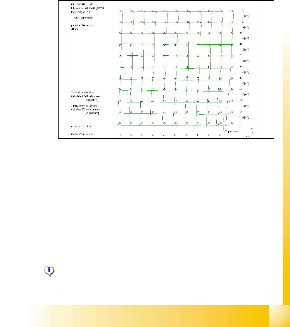
Fig. 10.2 - 11 Result of PCB mapping
The result are saved in the mapp _xy.ma ( x= number of the gantry , y= transport track)
10.2.6 Head mapping( C&P,Twin head)
With the head mapping the linearity of the X- and Y-guidance for C&P head movement is mea-
sured in the placement area.
The C&P head place the calibration tool on the mapping glass board exact to the nominal posi-
tions of the glass plate. The PCB-camera measure the placement accuracy of this placements for
the whole placement area.
➠ After the PCB mapping the placement head place at the theoretical positions of the PCB-map-
ping the calibration tool.
➠ The PCB-Camera look for the placement accuracy on the 4 fiducials at the calibration tool cor-
ner.
Note:
All described automatically calibration steps above, can you do manually step by step under the
sub menus (see chapter 12.1).
1 - 24
Student Guide SIPLACE HF/HF3
10 Sitest Edition 09/2005
24
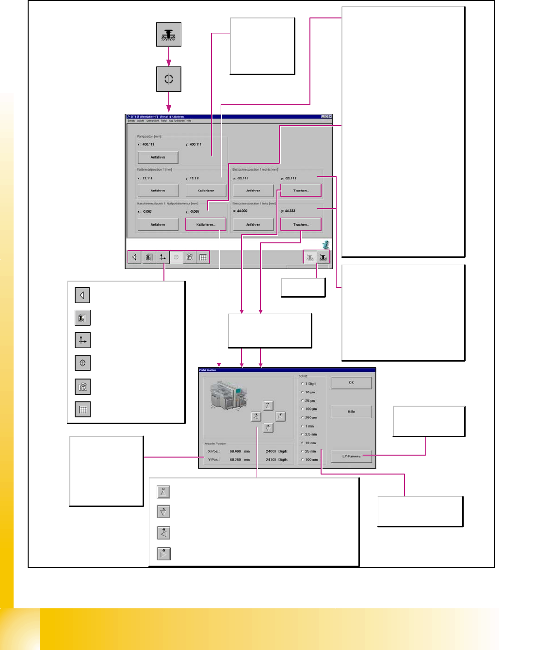
10.2.7 Single calibration steps (Flow charts e.g. SW 504 )
10.2.7.1 Gantry's Calibration Functions
Wählt das
Portal 1-2 aus.
Parkposition [mm]
x/y
Zeigt die x/y-Position
der Parkposition an.
Anfahren
Fährt das Portal in die
Parkposition.
Das Teachen der
Bestücknester kann nur
durchgeführt werden, wenn
der Transportmodus normale
Leiterplatte aktiviert ist.
Aktuelle Position
X-Pos.
Zeigt die beim Teachen
angefahrene x-Position
des jeweiligen Portals an.
Y-Pos.
Zeigt die beim Teachen
angefahrene y-Position
des jeweiligen Portals an.
Mit jedem Anklicken der Schaltfläche wird das aktive Portal um einen
Schritt der ausgewählten Schrittweite in die negative y-Richtung verfahren.
Mit jedem Anklicken der Schaltfläche wird das aktive Portal um einen
Schritt der ausgewählten Schrittweite in die positive y-Richtung verfahren.
Mit jedem Anklicken der Schaltfläche wird das aktive Portal um einen
Schritt der ausgewählten Schrittweite in die negative x-Richtung verfahren.
Mit jedem Anklicken der Schaltfläche wird das aktive Portal um einen
Schritt der ausgewählten Schrittweite in die positive x-Richtung verfahren.
Schritt
Auswahl der gewünschten
Schrittweite für das Verfahren
des Portals.
LP-Kamera
Schaltet die
Bildschirmanzeige auf die
Leiterplatten-Kamera um.
Kalibrierteilposition 1 (2) [mm]
x/y
Zeigt den bei der Kalibrierung ermittelten Wert
für die Position des Kalibrierteils in x-/y-Richtung
an. Der vorherige Wert wird in Klammern
angezeigt.
Anfahren
Fährt das aktive Portal mit der LP-Kamera über
die Kalibrierteilposition und schaltet zur
Überprüfung die Bildschirmanzeige auf die LP-
Kamera um. Das Kalibrierteil muss im Suchfeld
der Kamera zu sehen sein.
Kalibrieren
Ermittelt die Position des
Kalibrierteilmittelpunktes.
Maschinennullpunkt: Nullpunktkorrektur
[mm]
x/y
Zeigt den bei der Kalibrierung ermittelten Wert
für die Nullpunktkorrektur in x-/y-Richtung an.
Der vorherige Wert wird in Klammern angezeigt.
Anfahren
Fährt das Portal mit der LP-Kamera über die
Messbohrung für den Maschinennullpunkt und
schaltet zur Überprüfung die Bildschirmanzeige
auf die LP-Kamera um. Der Maschinennullpunkt
muss im Suchfeld der Kamera zu sehen sein.
Kalibrieren...
Öffnet das Dialogfenster Teachen, um die
Position des Maschinennullpunktes anzufahren.
Danach wird beim Kalibriervorgang der Wert für
die Nullpunktkorrektur der X- und Y-Achse
ermittelt.
Bestücknestposition 1 (2) rechts [mm]
Bestücknestposition 1 (2) links [mm]
(Doppeltransport)
x/y
Zeigt die beim Teachen ermittelte Position des
Bestücknestes in x-/y-Richtung an. Die
vorherige Position wird in Klammern angezeigt.
Anfahren
Fährt das aktive Portal mit der LP-Kamera über
die Bestücknestposition und schaltet zur
Überprüfung die Bildschirmanzeige auf die LP-
Kamera um. Die Bestücknestposition muss im
Suchfeld der Kamera zu sehen sein.
Aufruf der Ansicht für die
Leiterplatten-Mappingfunktionen
des Portals.
Aufruf der Ansicht für die
Leiterplatten-Kamerafunktionen
des Portals
Aufruf der Ansicht für die
Kalibrierfunktionen des Portals.
Aufruf der Ansicht für die
Achsfunktionen des Portals.
Aufruf der Ansicht für die
Funktionen des Portals.
Schaltet zur Grundansicht
zurück.