SG_FSE_SiplaceHF_HF3_00193901-05_eng.pdf - 第54页
1 - 28 S tudent Guide SIPLACE HF/HF3 2 Overview Edition 09/2005 28 2.2.12.1 St andard modul PCB Camera 2 Fig. 2.2 - 17 PCB camera under the Gantry (X-Axis) 1. PCB-camera - Op tics and illumination 2. Camera amplifier 3. …
1 - 27
Student Guide SIPLACE HF/HF3
Edition 09/2005 2 Overview
27
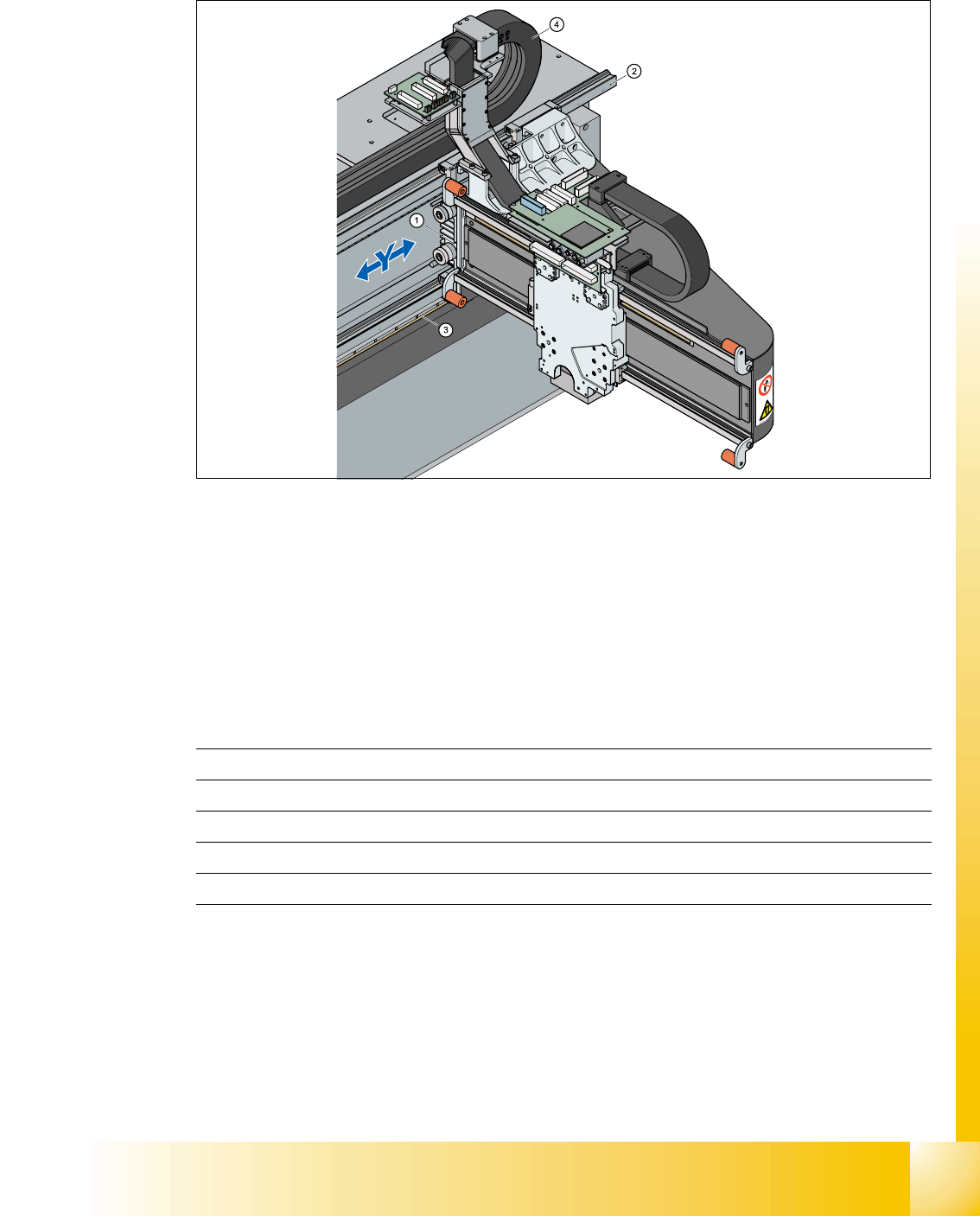
2.2.11 Construction Y-axis
2
Fig. 2.2 - 16 Construction Y-Axis
Legend The Y-Axis consist of the following main modules:
The Y axis is driven by a linear motor. The second part of the drive consists of a permanent mag-
net and is mounted at the machine frame. The primary part is screwed to the gantry arm (X-Axis).
Technical data Y-Axis 2
2.2.12 Cameras
Each 12-segment- and each 6-segment-Collect&Place-head contains your own component cam-
era. The finepitch-visionmodul for the Twin-Head is mounted on the machine frame.
(1) Linear drive Permanent magnet (2) Linear incremental encoder
(3) Linear guide (4) Trailing cable Y-Axis
Drive direct, Linear drive
Max. velocity 2,5 m/sec.
Travel range gantry 1430 mm
Lenght incremental encoder 1850mm
Resolution 1 µm
1 - 28
Student Guide SIPLACE HF/HF3
2 Overview Edition 09/2005
28
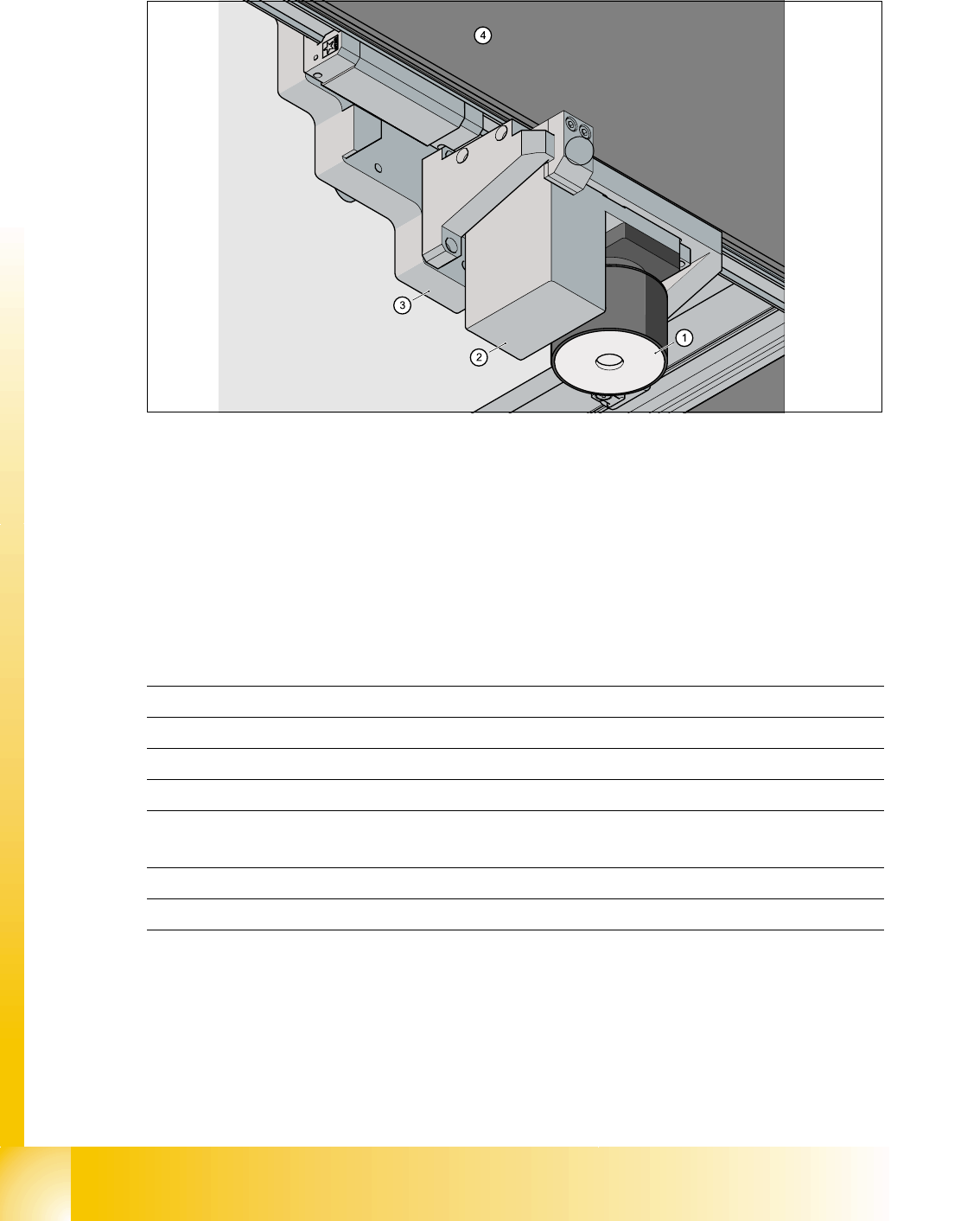
2.2.12.1 Standard modul PCB Camera
2
Fig. 2.2 - 17 PCB camera under the Gantry (X-Axis)
1. PCB-camera - Optics and illumination
2. Camera amplifier
3. Head mounting plate
4. Gantry
5. Damping unit
Technical Data 2
Option: Multicolor camera available (Camera type 18.sst) 2
5
PCB fiducial max. 3 per placement program
memory capacity for fiducial max. 255 PCB-fiducial - System fiducial ≥ 249
Image processing Geometric Alignment
Kind of illumination from above
Time for fiducial recognition per fiducial/
bad fiducial
0,4 s
Field of view 5,7 mm x 5,7 mm
Camera type .sst 5.sst
1 - 29
Student Guide SIPLACE HF/HF3
Edition 09/2005 2 Overview
29
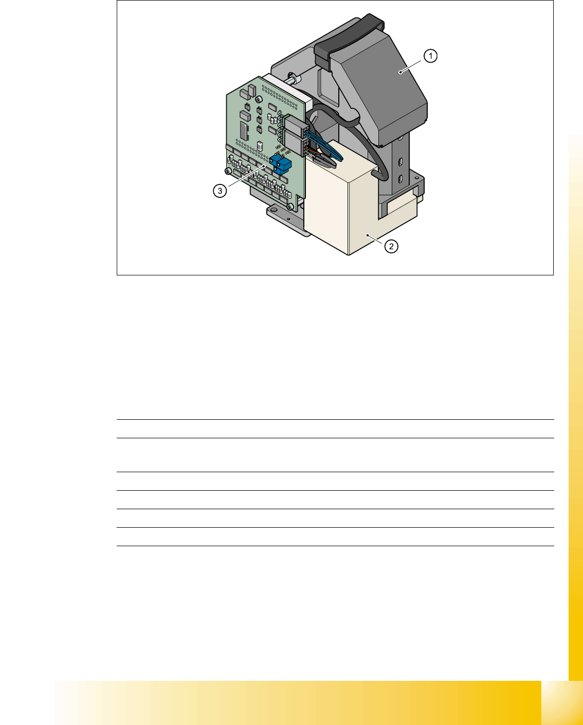
2.2.12.2 Component camera 12 segments C&P head
2
Fig. 2.2 - 18 Component camera standard on the 12-segment-Collect&Place-head
2
1. Component camera optics and illumination
2. Camera amplifier
3. Illumination control
Technical data 2
2
Option: DCA camera available (Camera type 14.sst) 2
Component size 0,6 mm x 0,3 mm bis 18,7 mm x 18,7 mm
Components shape 201 until PLCC44 incl. BGA, µBGA, Flip-Chip,
TSOP, QFP, PLCC, SO bis SO32, DRAM
Min. pitch 0,5 mm
Field of view 24 mm x 24 mm
Kind of illumination from above (3 level free programmable)
Camera type .sst 12.sst