SG_FSE_SiplaceHF_HF3_00193901-05_eng.pdf - 第130页
1 - 16 S tudent Guide SIPLACE HF/HF3 4 Services to the machine Edition 09/2005 16 4.2.4.4 V olta ges in the Power Supply Unit af ter switching on When the main switch is swit ched on , the following voltages are generate…
1 - 15
Student Guide SIPLACE HF/HF3
Edition 09/2005 4 Services to the machine
15
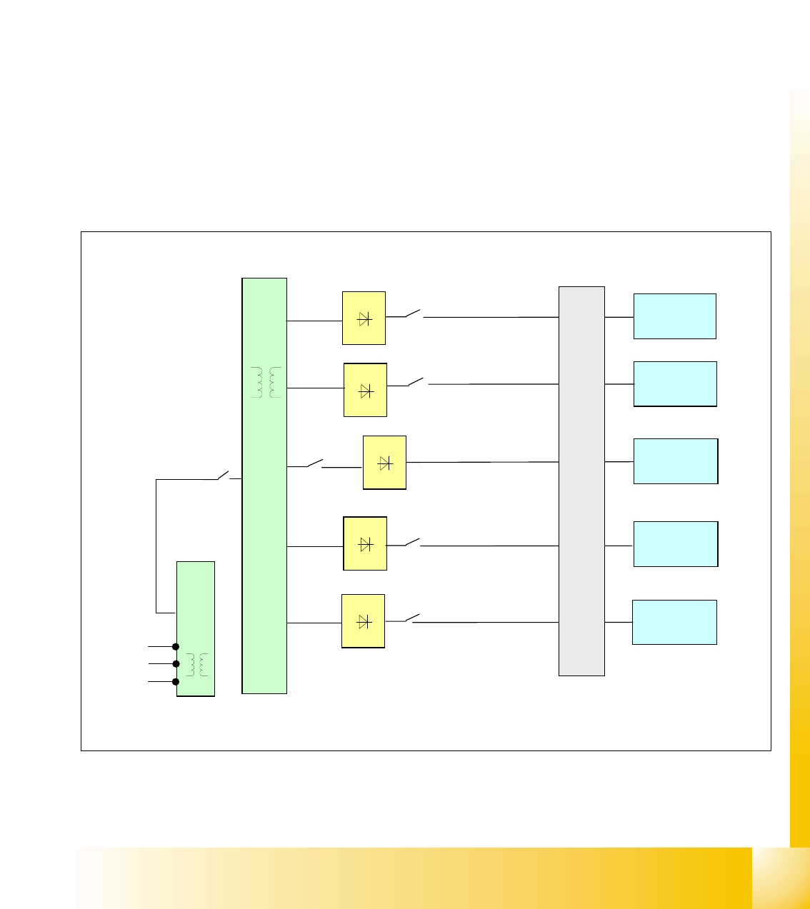
4.2.4.3 Transformer 2
The main reason for the transformer T2 is to power the Z- and Dp servos, protected by F6
4
The power supply unit provides the following supply voltages: 4
Secundary Transformer T2
– 40 VDC for the servo amplifiers the z and dp axes.
– 34 VDC for PCB handling system.
– 40 VDC for the component tables (30 V for feeder operation).
– 10 VDC for the component tables (5 V for logic).
– 28 VDC for the monitor.
– 24 VDC for the Y-axis motor cooling device.
Fig. 4.2 - 7 overview transformer 2
F8
PCB
Transport
Feeder
table
Monitor
cooling
Y-Axis
T1
L1
L2
L3
F7
T2
U4
F6
main power supply distributor
Z/Dp Servo
U5
U9
U10
F2
F13
U11
F14
40 VDC
34 VDC
24 VDC
28 VDC
40 VDC
T1
2
3
0
V

1 - 16
Student Guide SIPLACE HF/HF3
4 Services to the machine Edition 09/2005
16
4.2.4.4 Voltages in the Power Supply Unit after switching on
When the main switch is switched on, the following voltages are generated and may or may not
be switched (enabled, not enabled) through to the modules:
4
Voltages for the service socket 4
NOTE: The service socket can only be used if the placement system is connected to the main
power supply with a 5-conductor cable (L1, L2, L3, N, PE). 4
Voltage Module
260 VDC X/Y servo unit not enabled
150 VDC servo unit not enabled
34 VDC PCB handling system not enabled
24 VDC tape cutter not enabled
34 VDC SZ1 main power inrush current enabled
52 VDC DC/DC converter main power unit enabled
52 VDC illumination P&P camera (IC/FC cam-
era)
enabled
52 VDC power fail unit enabled
40 VDC Z/DP axes enabled
40 VDC component table enabled
28 VDC monitor enabled
24 VDC fan enabled
230 or 115 or 240 VAC service socket independent of the main
switch
230 VAC (Europe) input 3 x 400 VAC
115 VAC (U. S. A.) input 3 x 204 VAC
130 VAC (other) input 3 x 230 VAC
220 VAC (other) input 3 x 380 VAC
240 VAC (other) input 3 x 415 VAC
1 - 17
Student Guide SIPLACE HF/HF3
Edition 09/2005 4 Services to the machine
17
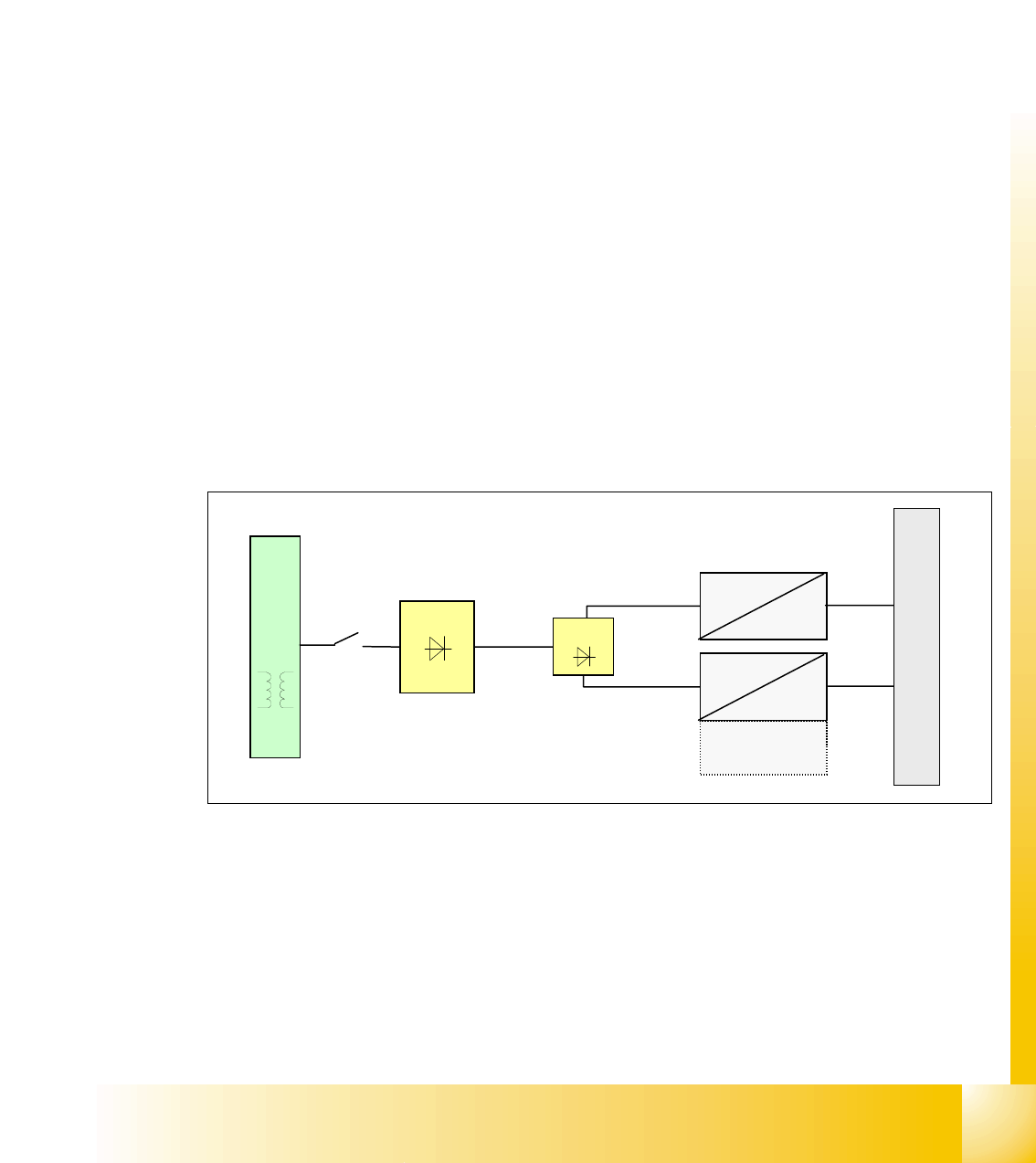
4.2.4.5 DC/DC Converter in Main Power Supply
Two DC/DC converter U20 and U30 generate the 24 VDC and 5 VDC, which are used overall in
the electrical system, are located in the main power supply module.
DC/DC converter U20:
1.+24 VDC converted from 52 VDC is split into 4 path
– path 1: power for servo enable
– path 2: SSK relay K6
– path 3: for inrush current limiter servo
– path 4: mainly used: general use of 24V all over the machine
2.+24 VDC converted from 52 VDC is split into 2 path only on the HF3 machine:
– ventilator for the axis unit
– PCB transport control board
DC/DC converter U30:
5 VDC logic power, which his mainly used in the overall machine
Fig. 4.2 - 8 DC/DC converter main power supply
T1
U7
52 VDC
24 VDC
52 VDC
5 VDC
U6
F10
main power supply distributor
24 VDC for
HF3