00194614-08 Trainingsdoku. SG X-Serie_X4i SW70x (AL2)_EN.pdf - 第100页
Communication and Control CAN Bus Communication with Axis Controller CAN Bus Student Guide SIPLACE X-Serie and X4I SW70x (AL2) 100 CAN Bus- Control led Func tions on the Twin Head 4.3.4.3 CAN Bus-Controlled Functions on …
Communication and Control
CAN Bus CAN Bus Processor Board C&P Head
99 Student Guide SIPLACE X-Serie and X4I SW70x (AL2)
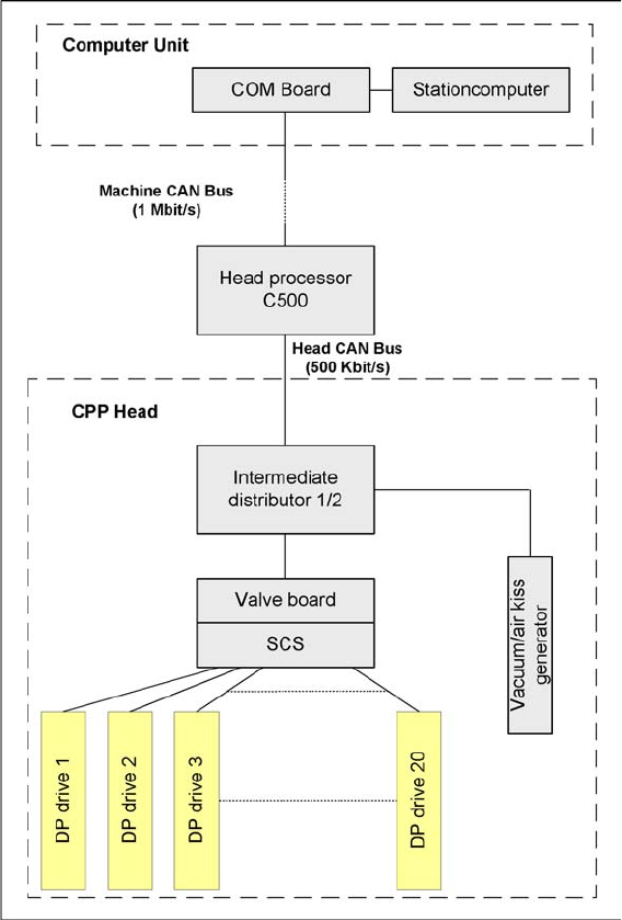
CAN Bus-Controlled Functions on the CPP Head
4.3.4.2 CAN Bus-Controlled Functions on the CPP Head
Communication TQM module
Communication and Control
CAN Bus Communication with Axis Controller CAN Bus
Student Guide SIPLACE X-Serie and X4I SW70x (AL2) 100
CAN Bus- Control led Func tions on the Twin Head
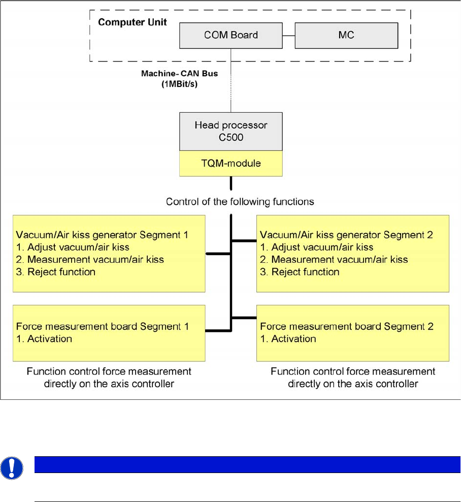
4.3.4.3 CAN Bus-Controlled Functions on the Twin Head
Function on the Can Bus Processor Twin head
The CAN bus processor board is no longer installed on each Twin segment, as in the case of the HF
machines. It can now be found at a central location on the head processor board C500.
CAN Bus Communication with Axis Controller
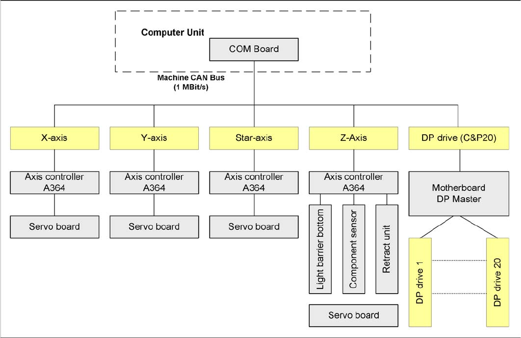
4.3.5 CAN Bus Communication with Axis Controller
The communication between the axis controller modules is now achieved using the CAN Bus. All the
information exchanged between these modules is transmitted via the CAN bus (e.g. axis parameter,
target position, end position signal, ...).
NOTICE
The status of the 16 bit processor board is indicated on the 7-segment display.
Normal status on the display is: "." flashes. (for description see Section C&P Head).
Communication and Control
CAN Bus CAN Bus Communication with Axis Controller
101 Student Guide SIPLACE X-Serie and X4I SW70x (AL2)
Overview axis controller