00194614-08 Trainingsdoku. SG X-Serie_X4i SW70x (AL2)_EN.pdf - 第337页
TwinHead Settings Parameter and Calibrations 337 Student Guide SIPLACE X-Serie and X4I SW70x (AL2) The 42V are use for the illumination of the stationary cameras. When replacing the Vision DC/DC converter, obse rve the f…
TwinHead
Description of Boards on the TwinHead Settings
Student Guide SIPLACE X-Serie and X4I SW70x (AL2) 336
to 5) DIP switch
Mechanical Ad justment of th e Z Axis Incre mental Encode r
9.4.1.6 Mechanical Adjustment of the Z Axis Incremental Encoder
Vision DC/DC Converter
9.4.1.7 Vision DC/DC Converter
The function of the Vision DC/DC converter is to provide the 42V voltage supply for the stationary
cameras.
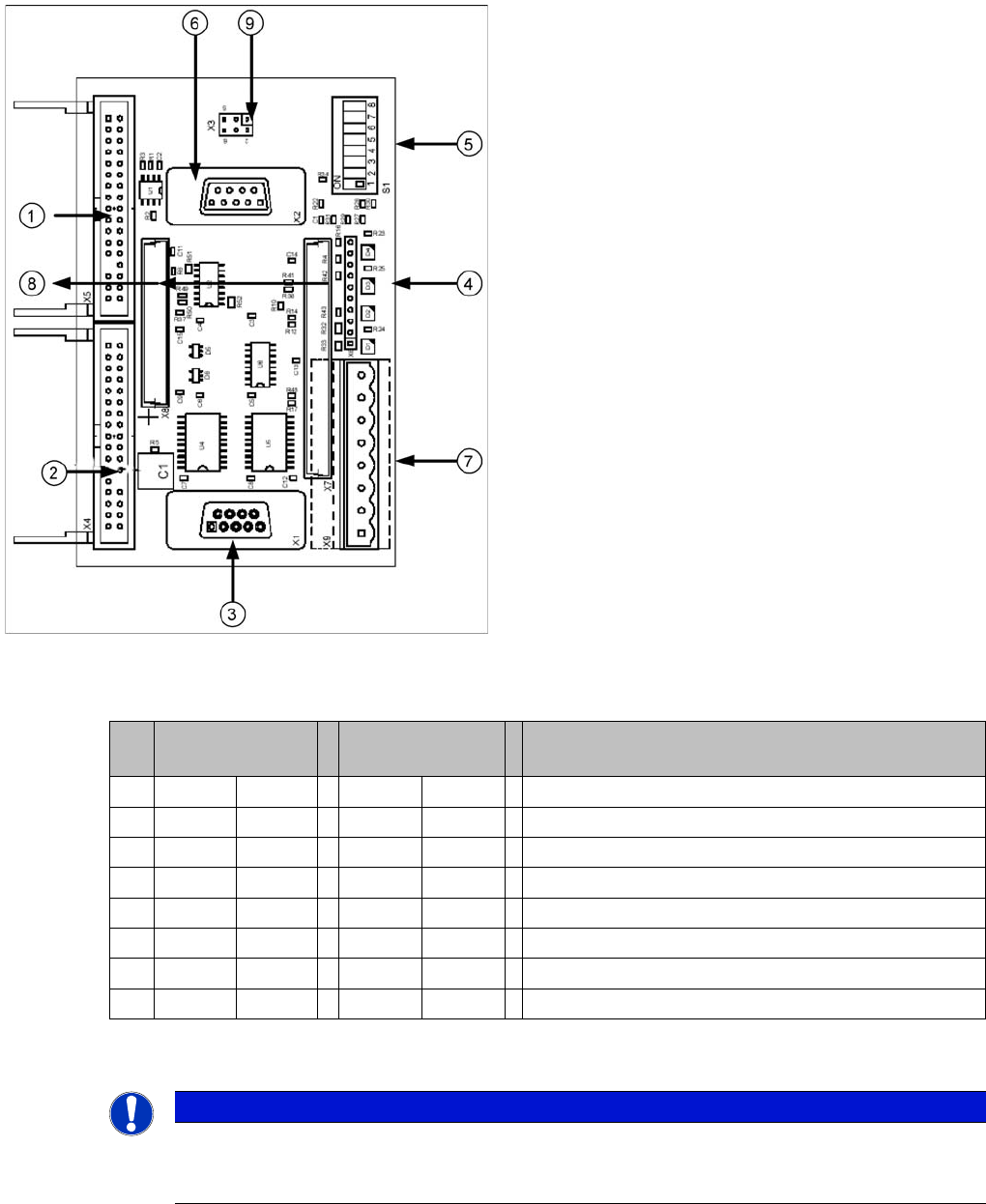
Vision control board TwinHead IC camera
Legend
1. Connector for FC Camera illumination
2. Connector for IC Camera illumination
3. Service connector
4. LEDs (downwards D4 - D1)
+5 V/-15 V/+15 V/+40 V
5. DIP switch
6. Connector CAN Bus
7. Voltage supply for Vision control
Connector for DC/DC converter (sector 2)
DC/DC distributor (sector 4)
8. Connectors for 16 bit CAN Bus processor (TQM
modules)
9. Flash signal (not used for Siplace Vision)
S Sector 2
Main distributor
Sector 4
Subdistributor
Description
1 OFF OFF CAN terminating resistor - 120 Ohm not set
2 OFF OFF Reset
3 OFF OFF Bootstrap
4 OFF OFF TEST
5 OFF ON P1 address switch, gantry ID 1
6 ON ON P0 address switch, gantry ID 2
7 OFF OFF CAN - ID 1
8 OFF OFF CAN -ID 0
NOTICE
The incremental encoder on the Z axis must be adjusted to a distance of 0.4 mm to the
incremental scale. Please adjust the incremental encoder parallel to the incremental scale.
After fitting, check the Z axis track signals (see Section Component Handling).
TwinHead
Settings Parameter and Calibrations
337 Student Guide SIPLACE X-Serie and X4I SW70x (AL2)
The 42V are use for the illumination of the stationary cameras.
When replacing the Vision DC/DC converter, observe the following settings, which depend on your
installation location (main/subdistributor).
Parameter and Calibrations
9.4.2 Parameter and Calibrations
Overview of C alibration Step s and Paramete rs
9.4.2.1 Overview of Calibration Steps and Parameters
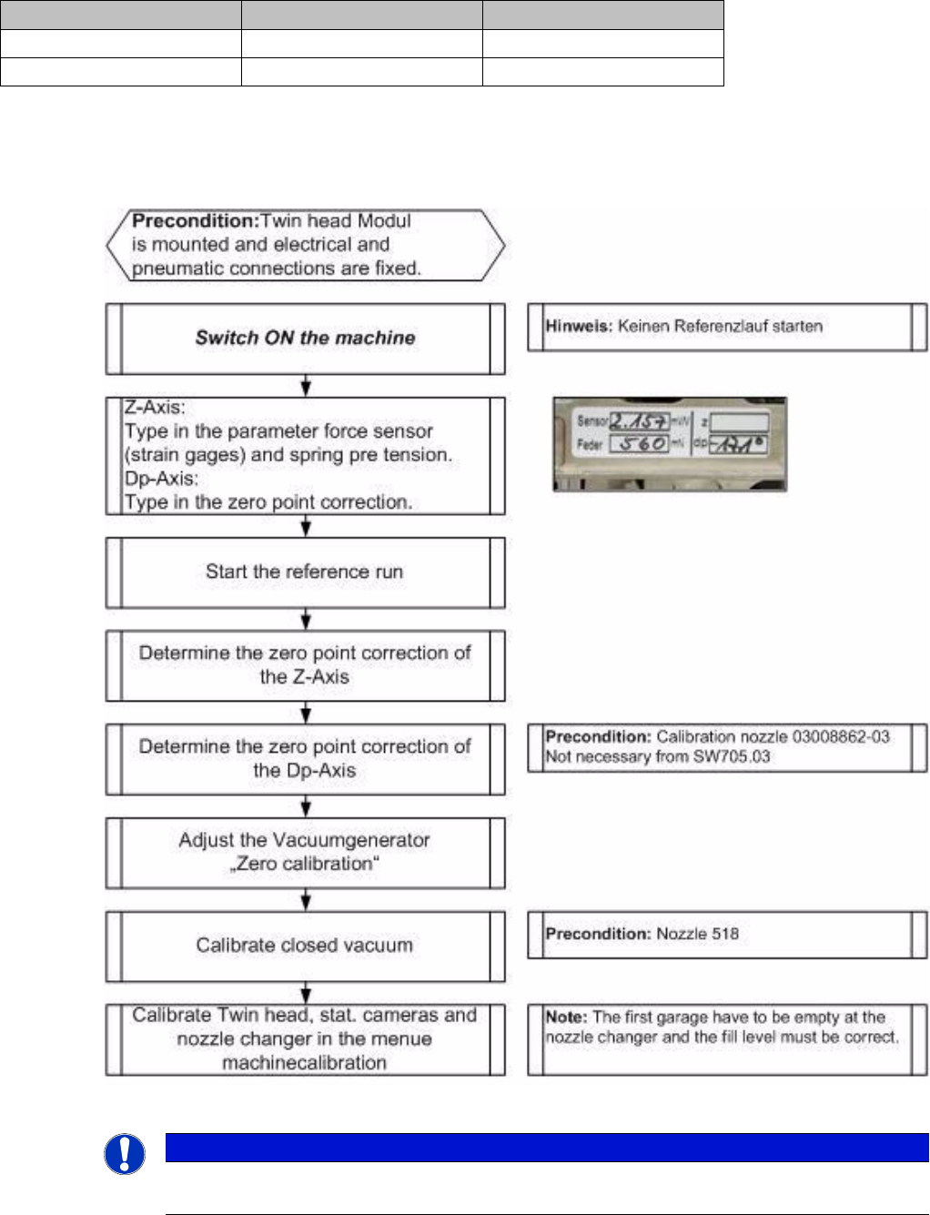
Overview of calibration steps and parameters
Main distributor Subdistributor
Bypass 1 (wire jumper) 10 - 13 6 - 13
Bypass 2 (wire jumper) 11 - 12 4 - 12
NOTICE
These steps are necessary during the first initial setup or a replacement of the TwinHead
module. The detailed description can be found on the following pages.
TwinHead
Parameter and Calibrations Settings
Student Guide SIPLACE X-Serie and X4I SW70x (AL2) 338
Procedur e
9.4.2.2 Procedure
Entering Parameters
Entering Parameters
Determining the Z Axis Zero Point Correction
Determining the Z Axis Zero Point Correction
After performing a head exchange or service work to the
TwinHead, the following settings are required for
successful calibration of the TwinHead.
1. Entering Parameters
2. Calibrate Z zero point
3. Calibrate Dp zero point
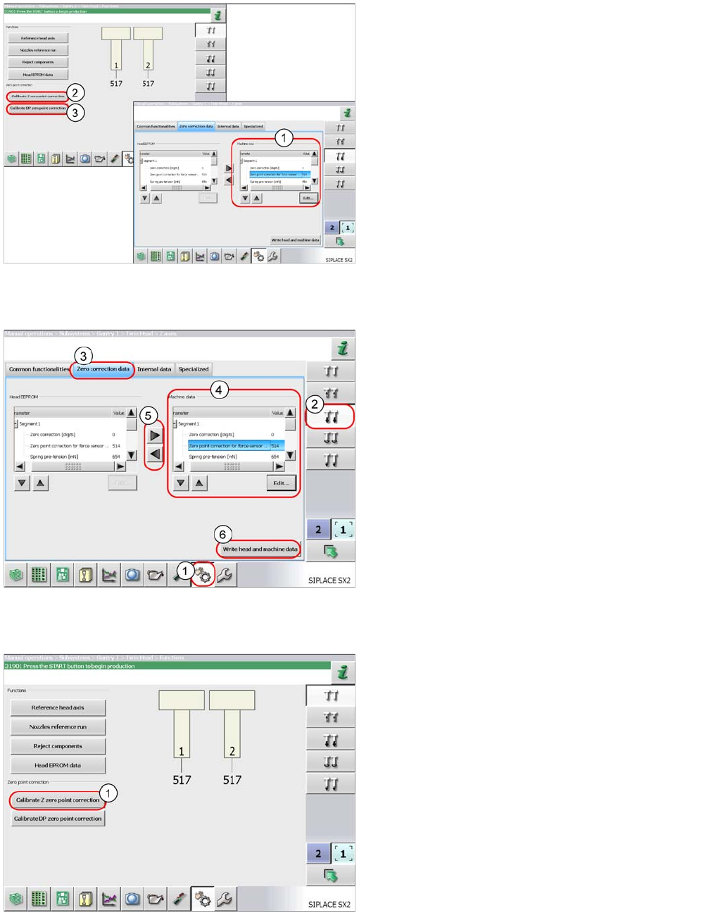
► Log in as service (customer).
► Select Sensors and Functions (1).
► Select the Z axis (2).
► Switch over to the Zero correction data tab (3).
► Mark the parameters at Machine data (4) and
select Edit.
Enter the values for both segments 1 and 2.
Apply the values to the head EEPROM with the arrow
buttons (5).
► Save the values with the Write head and
machine data button (6).
Perform a complete reference run. The TwinHead is
positioned over the fixed conveyor edge to determine the
Z axis zero point correction value.
► To determine the Z axis zero point correction value,
select the Calibrate Z zero point
correction button (1).