00194614-08 Trainingsdoku. SG X-Serie_X4i SW70x (AL2)_EN.pdf - 第475页
MTC2 MTC2 Calibration and Settings Adjustments Lifting Axes 475 Student Guide SIPLACE X-Serie and X4I SW70x (AL2) Adjustments L ifting Axe s 13.3.3 Adjustment s Lifting Axes Overview of the lifting axes Legend Belt tensi…
MTC2
SITEST Calibration Flow Charts MTC2 Calibration and Settings
Student Guide SIPLACE X-Serie and X4I SW70x (AL2) 474
Machine Data
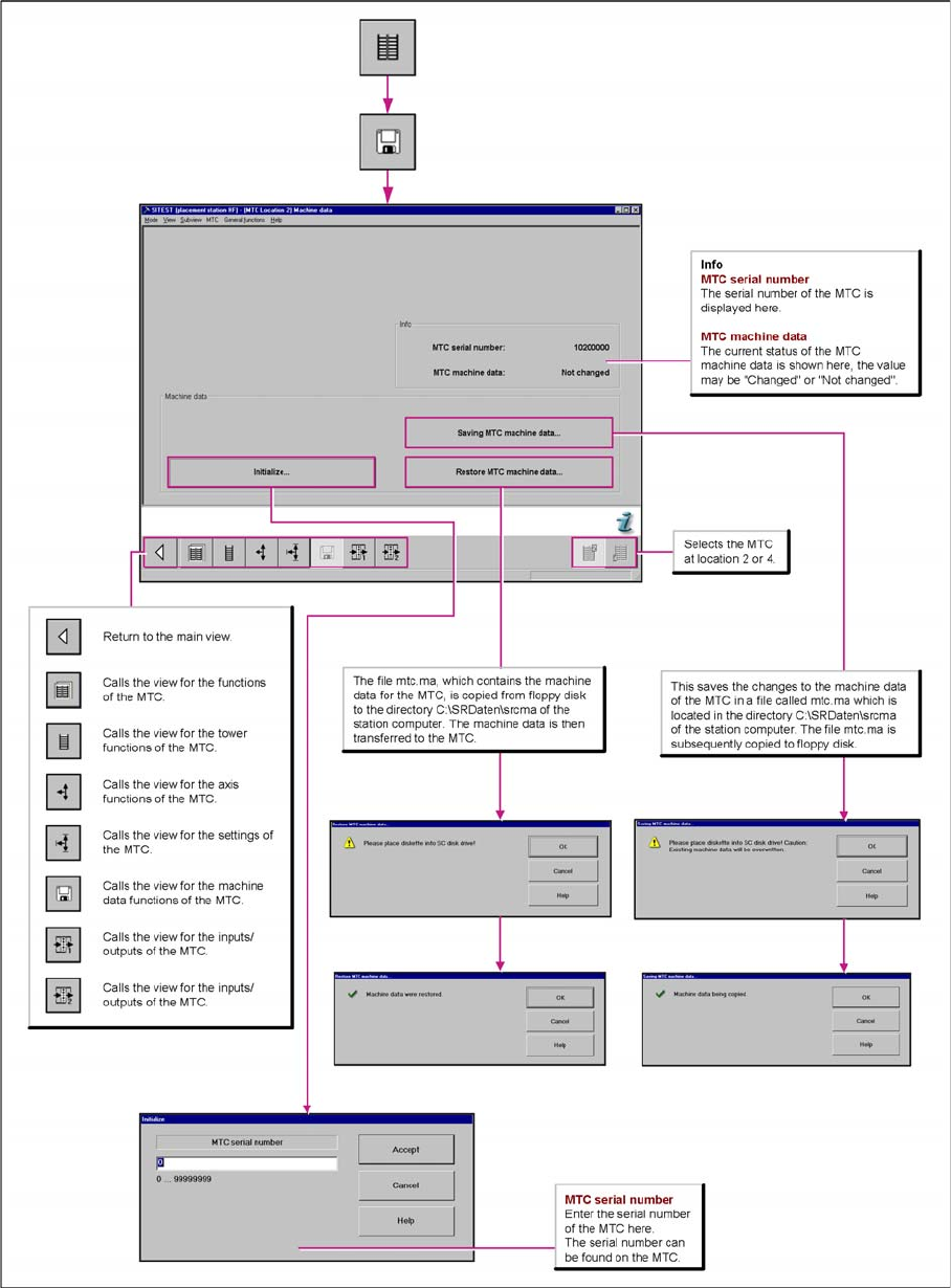
13.3.2.3 Machine Data
Save Machine-Data: With the SW 601, it is not possible to save the data onto the floppy disc.
Now you can choose a folder and save the mtc.ma (e.g. Memory Stick)
MTC2
MTC2 Calibration and Settings Adjustments Lifting Axes
475 Student Guide SIPLACE X-Serie and X4I SW70x (AL2)
Adjustments Lifting Axes
13.3.3 Adjustments Lifting Axes
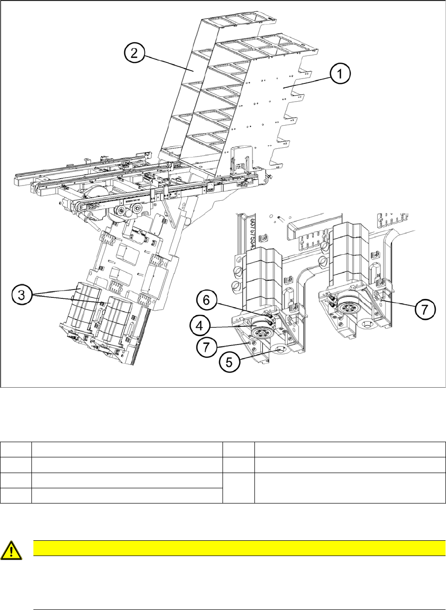
Overview of the lifting axes
Legend
Belt tensio n
13.3.3.1 Belt tension
Tools and Equipment
Tools and Equipment
▪ Belt frequency measurement device (inductive)
▪ 2 belt tension strips
1 Lifting axis tower 1 5 Spindle (shown here for tower 2)
2 Lifting axis tower 2 6 Inductive sensors (shown here for tower 2)
3 Servo motors of the lifting axes 7 Holes for the measurement head of the belt
frequency measuring device
4 Dual toothed belt (shown here for tower 2)
CAUTION
The construction of the lifting axis was change since 05.2005. This means, new spindle, spindle
with counter bearing, motor lifting axis, gear on the motor and therefore new parametersets for
Masterdrives. The MTC2 has the version number 02. The belt tension for the lifting axis was
change, please note!
MTC2
Adjustments Lifting Axes MTC2 Calibration and Settings
Student Guide SIPLACE X-Serie and X4I SW70x (AL2) 476
▪ 1 set of Allen keys
▪ 1 set of open-ended wrenches
Preparat ions
Preparations
► Empty the MTC2 completely (see the User Manual).
► Move the lifting axis into its bottom position.
► Remove the left cover in front of the electronics board and the covers on the right and the left in front
of the Masterdrives.
► Switch the motor protection switch off (see ).
► To relieve the tension the toothed belts, loosen the brake on the servo motor in the following way to
rest the lifting axis on the buffer:
⇨ Check whether the MTC2 has been switched off and is isolated from the power supply.
⇨ Disconnect the terminal connector for the external signals from the lifting axis master drive.
⇨ Move the cable from Pin 3 to Pin 1.
⇨ Attach the connector.
⇨ Connect the MTC2 to the power supply and switch it on.
⇨ The lifting axis audibly moves a distance of a few mm up to the buffer.
► Check that the lifting axis is actually at its end position.
► Reconnect the cable as it was originally in the following way:
⇨ Switch off the MTC2 and isolate it from the power supply.
⇨ Disconnect the terminal connector for the external signals from the lifting axis master drive.
⇨ Move the cable from Pin 1 to Pin 3.
⇨ Attach the connector.
► Switch the motor protection switch on.
► Attach the covers.
► Undock the MTC2 from the SIPLACE station (see User Manual).
► Crank up the MTC2 in a clockwise direction until it stops.
See also
13.3.3.1.1 Tools and Equipment [ ➙ 475]
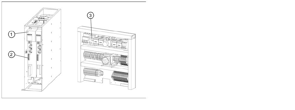
Connections to the Masterdrives of the lifting axes
Legend
1. Masterdrive, lifting axis (shown here for tower 1)
2. Connection terminal for external signals
3. Motor protection switch on the electronics board