00194614-08 Trainingsdoku. SG X-Serie_X4i SW70x (AL2)_EN.pdf - 第153页
Energy and Compressed Air Supply Power supply Main distributor ( X series from Ma. No. B326) 153 Student Guide SIPLACE X-Serie and X4I SW70x (AL2) ▪ Handing over constituent (A2): Design ation X30 r a and X31ra Placement…
Energy and Compressed Air Supply
Naming Convention of Connectors and Cables Power supply
Student Guide SIPLACE X-Serie and X4I SW70x (AL2) 152
Power supply
5.2 Power supply
Main power supply unit
Legend
Naming Convention of Connectors and Cables
5.2.1 Naming Convention of Connectors and Cables
The wiring on the SIPLACE X is highly structured. Every cable, connection or distributor uses an exact
term, which refers to the sections and units in question:
Sector 2: term q+
▪ Main-distributor section 2: Designation X1qa, X2qa, X3qa, ...
▪ CAN I/O module (A1): Designation X1qb, X2qb, X3qb, ...
▪ Vision DC/DC converter (A3): Designation X1qc, X2qc, X3qc, ...
▪ Vision control module (A4): Designation X1qd, X2qd, X3qd, ...
▪ Circuit board 8-fold AND operation (A5): Designation X1qe, X2qe and X3qe
Sector 4: term r+
▪ Sub-distributor section 4: Designation X1ra, X2ra, X3ra, ...
▪ CAN I/O module (A1): Designation X1rb, X2rb, X3rb, ...
▪ Vision DC/DC converter (A3): Designation X1rc, X2rc, X3rc, ...
▪ Vision control module (A4): Designation X1rd, X2rd, X3rd, ...
▪ Circuit board 8-fold AND operation (A5): Designation X1re, X2re and X3re
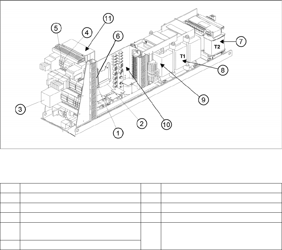
1 DC/DC Converter 24 V 7 Transformer T2
2 DC/DC Converter 5 V and additional 24V 8 Transformer T1
3 Protective contactor combination K6 (SSK) 9 Fuse F61 – Fuse F142
4 Fuse F5 (10A) for star axis 10 Main distributor voltage supply
5 Fuse F11(1A) for transformer inrush
current limitation board
11 Inrush current limitation board
a: Transformer: EST
b: Servo: Ess
6 Discharge inductor L20
Energy and Compressed Air Supply
Power supply Main distributor (X series from Ma. No. B326)
153 Student Guide SIPLACE X-Serie and X4I SW70x (AL2)
▪ Handing over constituent (A2): Designation X30ra and X31ra
Placement head gantry 1: Designation a+
▪ Gantry distributor: 00 353593 aa
▪ Gantry interface: 00 363330 ab
▪ Head interface: 03000900 ac
▪ Vision board: 03 321469 au
Placement head gantry 3: Designation b+ / c+
(in machines up to MA No. xx the designation is b+ /
in machines from MA No. xx the designation is c+)
▪ Gantry distributor: 00 353593 ba
▪ Gantry interface: 00 363330 bb
▪ Head interface: 03000900 bc
▪ Vision board: 03 321469 bu
Placement head gantry 4: Designation d+
▪ Gantry distributor: 00 353593 da
▪ Gantry interface: 00 363330 db
▪ Head interface: 03000900 dc;
▪ Vision board: 03 321469 du;
▪ Computer unit: X1p+
Main distrib utor (X seri es from Ma. N o. B326)
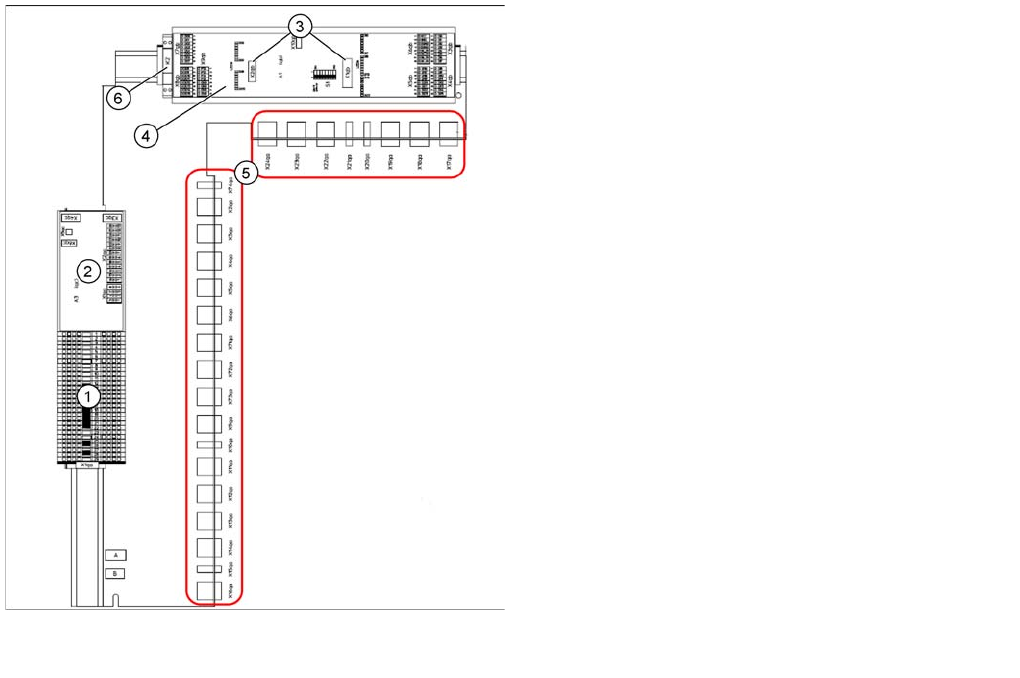
5.2.2 Main distributor (X series from Ma. No. B326)
Main distributor (X series from Ma. No. B326, X4I)
[03046225-xx]
Legend:
1. Terminal strip X1qa (GND, +5 V, +15 V, -15 V,
+24 V, various signals)
2. DC/DC converter for illumination of all cameras
(PCB, component and stationary cameras) in
placement area 2
3. Socket for Interface 1-Wire CAT5
4. CAN-Bus I/O module (A1)
5. Connector block (connection X2qa - X6qa, X71qa -
X74qa and X9qa - X24qa)
6. Relay K2 switches the compressed air supply for the
placement heads off (can be configured in the station
software)
Energy and Compressed Air Supply
Subdistributor (X Series from Ma. No. B326) Power supply
Student Guide SIPLACE X-Serie and X4I SW70x (AL2) 154
Subdistributo r (X Series from Ma. No. B326)
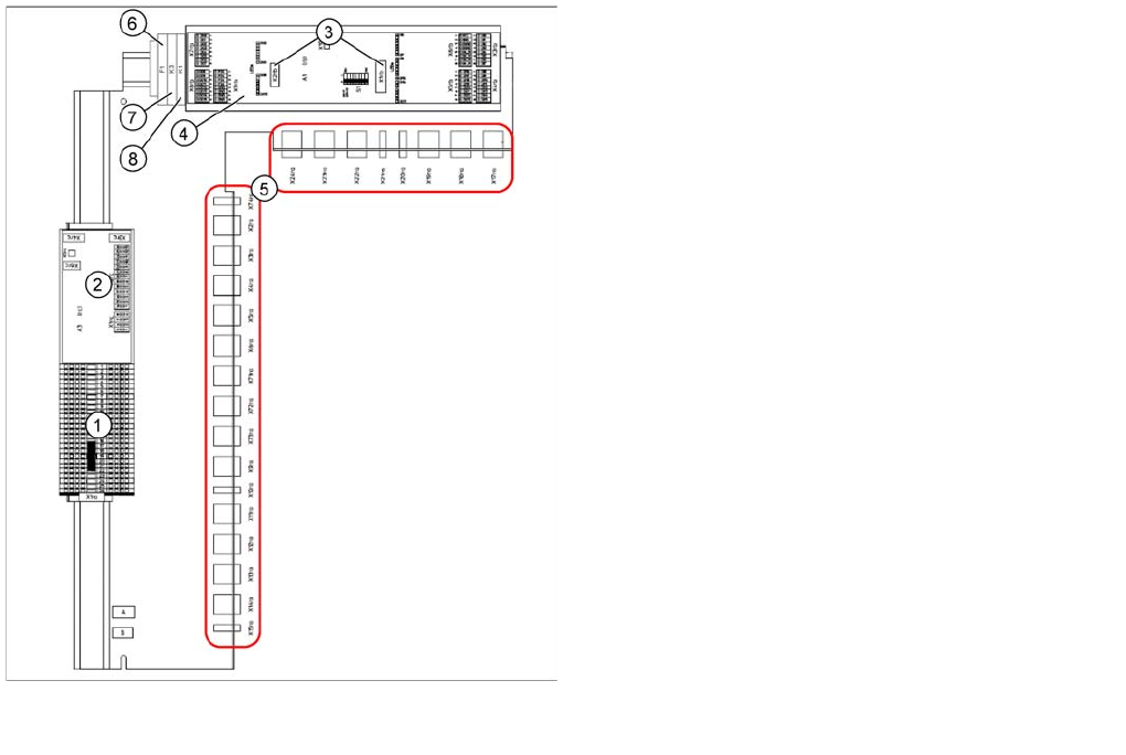
5.2.3 Subdistributor (X Series from Ma. No. B326)
Power supply
5.2.4 Power supply
The main power supply unit is mounted on a compact slide-in module, and located on the left side of the
machine. When viewed from the outside only the red main power switch is visible.
A lockable door prevents access to the power supply.
With the open cover, the state of the following protective devices can be quite easily monitored.
▪ Motor Circuit Breaker
▪ Main contactor
▪ Safety relay
▪ Power circuit breaker
▪ Protective contactor combination (SSK)
The following work must be performed to adjust the power supply to the country-specific requirements
(see also the conversion instructions for power supplies):
1. Replace the motor protecting switch
2. Replace the power supply cable (country-specific)
3. At the primary end of transformer T1, the terminal connectors (U, V, W) must be reconnected to fulfill
the country-specific voltage requirements.
4. Reconnect the connector on the inrush limitation board transformer.
Subdistributor (X Series from Ma. No. B326, X4I)
[03046226-xx]
Legend:
1. Terminal strip X1ra (GND,+5 V,+15 V,-
15 V,+24 V,+52 V, various signals)
2. DC/DC distributor for illumination of all cameras
(PCB, component and stationary cameras) in
placement area 1
3. Socket for Interface 1-Wire CAT5
4. CAN I/O module (A1)
5. Connector block (connection X3ra - X6ra, X71ra-
X74ra, X10ra - X24ra)
6. F1: Fuse for hood fan
7. K3: Relay for hood fan
8. K1: This relay switches the main valve in the
pneumatic unit.