00194614-08 Trainingsdoku. SG X-Serie_X4i SW70x (AL2)_EN.pdf - 第330页
TwinHead Preparations for Placement (Module 2 Component ) T winHead Pickup and Place Cycle Student Guide SIPLACE X-Serie and X4I SW70x (AL2) 330 Placement (Module 1 Component) 9.3.6.1 Placement (Module 1 Component) Prepa…
TwinHead
TwinHead Pickup and Place Cycle Component centering module 1 and 2
329 Student Guide SIPLACE X-Serie and X4I SW70x (AL2)
Component centering module 1 and 2
9.3.5 Component centering module 1 and 2
Preparations for Placement (Module 1 Component)
9.3.6 Preparations for Placement (Module 1 Component)
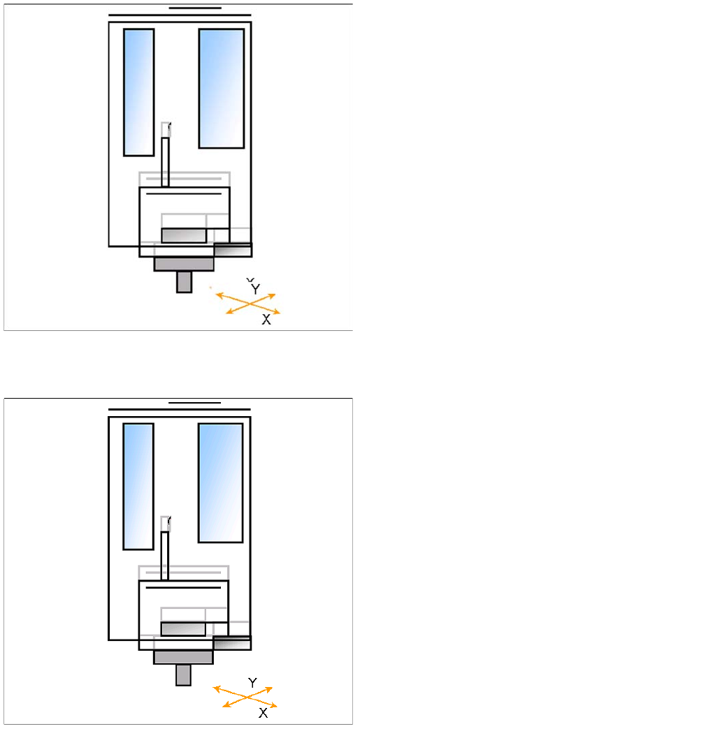
▪ X/Y axes position module 1 via the IC camera.
▪ Z axis moves until the underside of the components
lies in the focus level.
▪ IC-camera illumination is activated.
▪ Move Z Axis again upwards.
▪ Centering 1st component (near placement angle) is
finished
▪ The X/Y axes position module 2 over the IC camera.
▪ Z axis moves until the underside of the components
lies in the focus level.
▪ IC-camera illumination is activated.
▪ Move Z Axis again upwards.
▪ The X/Y gantry axes move to the corrected
placement position.
▪ The D-axis rotates by the placement angle correction
value.
TwinHead
Preparations for Placement (Module 2 Component) TwinHead Pickup and Place Cycle
Student Guide SIPLACE X-Serie and X4I SW70x (AL2) 330
Placement (Module 1 Component)
9.3.6.1 Placement (Module 1 Component)
Preparations for Placement (Module 2 Component)
9.3.7 Preparations for Placement (Module 2 Component)
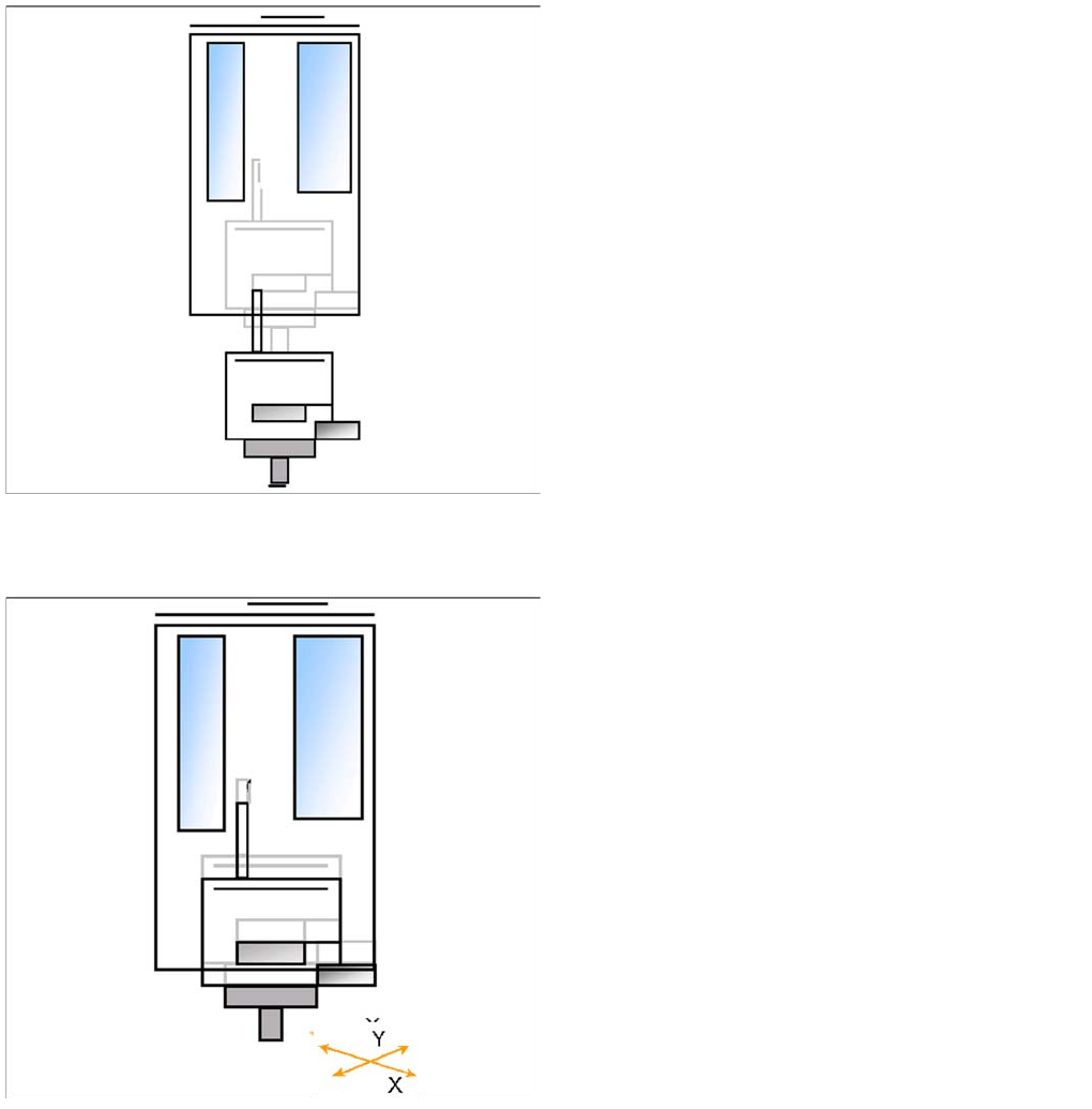
▪ The Z axis moves downwards in standard mode (2 N
contact force).
▪ The Force increase up to the programmed level after
contact of the component on the PCB.
▪ With this Force signal the End signal is set. The air
blast control is activated too.
▪ At air blast level for placement ..
▪ The next pickup sequence is prepared for module 2.
▪ The X/Y gantry axes moves to the actual (corrected)
placement position.
▪ The D-axis rotates by the placement angle correction
value.
TwinHead
Settings Description of Boards on the TwinHead
331 Student Guide SIPLACE X-Serie and X4I SW70x (AL2)
Placing the Component (Module 2 Component)
9.3.7.1 Placing the Component (Module 2 Component)
Settings
9.4 Settings
Descript ion of Boards on t he TwinHe ad
9.4.1 Description of Boards on the TwinHead
All adjustments described in this chapter are head specific and apply here for the TwinHead.
Head Adapter for TwinHead (for X Series with A364)
9.4.1.1 Head Adapter for TwinHead (for X Series with A364)
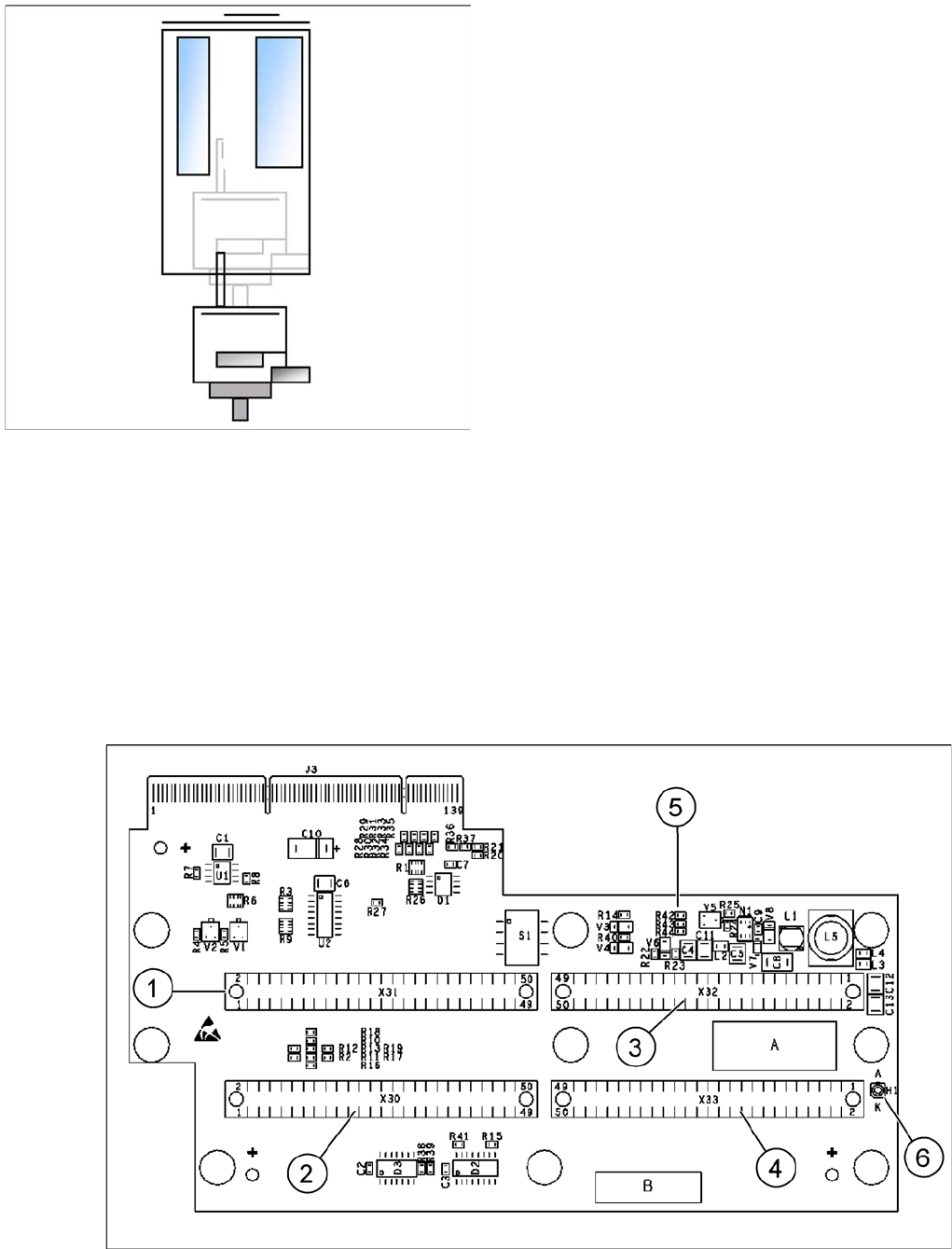
The head adapter board connects the head interface from the bottom side directly. The main boards of
TwinHead segments 1 and 2 are connected directly via 2 flat ribbon cables, each. This head adapter
must be changed for head modularity, if you use a C&P head.
Head adapter for TwinHead
▪ The Z axis moves downwards in standard mode (2 N
contact force).
▪ The Force increase up to the programmed level after
contact of the component on the PCB.
▪ With this Force signal the End signal is set. The air
blast control is activated too.
▪ At air blast level for placement Z Axis move upwards
with Standard profile.
▪ The next pickup sequence is prepared for module 1.
* Troubleshooting: If the air blast pressure is not reached
during placement, a vacuum check will be performed in
the Z axis up position, to see whether the component has
been placed or not.