00194614-08 Trainingsdoku. SG X-Serie_X4i SW70x (AL2)_EN.pdf - 第269页
Collect, Pick and Place Head (CPP) Overview Overview of Parts 269 Student Guide SIPLACE X-Serie and X4I SW70x (AL2) Pressure Control Valve - Function Pressure Control Valve - Function Z Axis 8.2.7.3 Z Axis ▪ The secondar…
Collect, Pick and Place Head (CPP)
Overview of Parts Overview
Student Guide SIPLACE X-Serie and X4I SW70x (AL2) 268
Overview of Parts
8.2.7 Overview of Parts
Front plate
8.2.7.1 Front plate
See also
8.2.7.2 Pressure control valve (digital) [ ➙ 268]
Pressure c ontrol valve (d igital)
8.2.7.2 Pressure control valve (digital)
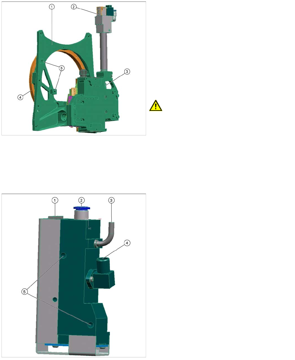
Legend
1. Front plate
2. Return cylinder
3. Z axis with jaws and measuring system
4. Raceway
5. Fixture for pressure control valve
Front plate
The front plate of the CPP head is fixed to the head
housing with four screws and needs to be removed as a
whole unit for service purposes.
CAUTION! Do not dismantle any of the
attachments from the front plate, as all attachments are
coordinated with one another and require special settings
(except the pressure control valve, see ).
LINK
Legend
1. Energy and data supply
2. Compressed air connection
3. Vacuum/air blast outlet for pickup/placement circuit
4. Discharged air for cooling the X motor (SX4 and X
series machines only).
5. Fixture for fastening the pressure control valve to the
front plate
▪ The pressure control valve supplies the pickup/
placement circuit with vacuum during the pickup
process and switches over to air blast during
placement.
▪ The digital pressure control valve can be adjusted
infinitely between max. vacuum and max. air blast in
the pickup/place circuit.
▪ The complete press control valve can be replaced
during service work.
Collect, Pick and Place Head (CPP)
Overview Overview of Parts
269 Student Guide SIPLACE X-Serie and X4I SW70x (AL2)
Pressure Control Valve - Function
Pressure Control Valve - Function
Z Axis
8.2.7.3 Z Axis
▪ The secondary part (magnets) of the linear motor is the moveable part on the z-axis. The primary
part is fixed. Benefit: There is no power supply cable of the motor that moves up and down with the
Z axis.
▪ The jaws are installed on the secondary part of the Z motor, for mechanical docking of the DP drives.
▪ The retract unit is integrated in the Z-Axis frame and is responsible for protecting the Z-axis from
damage if there is no power supplied.
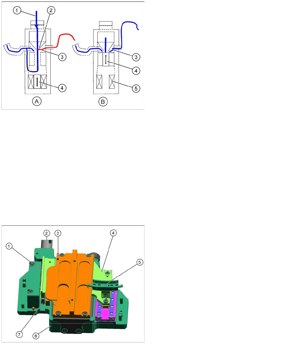
Legend
A : Piston setting for max. vacuum during pickup
B : Piston setting for air blast during placement
1. Compressed air inlet
2. Venturi nozzle
3. Vacuum or air blast outlet, depending on piston
setting
4. Pistons
5. Motor
▪ After initialization, the piston is in a central position, in
which neither vacuum nor air blast is applied to the
nozzle.
▪ During pickup, the piston is always in the Open
position, so that maximum vacuum is generated and
is present at the nozzle. The switchover time
(pressure build up time) between max. vacuum of –
850 mbar to max. air blast of +200 mbar ≤ 12 ms.
▪ The function Early vacuum should always be
switched on for the CPx head. However, if this
function is switched off, the piston will be in the "open
position". The vacuum will only be switched on again
after the "light barrier down" signal has been issued .
-> 2 additional switching steps -> time loss.
Legend
1. Incremental measurement system, resolution 0.5 µm
2. Retract unit
3. Lubrication point for Z axis support ball bearing
4. Secondary part with magnets
The secondary part is fitted to the Z axis.
5. Jaws
The jaws are fitted to the linear guidance of the Z axis.
6. Linear motor, primary part
7. Actuator on the retract unit
Collect, Pick and Place Head (CPP)
Overview of Parts Overview
Student Guide SIPLACE X-Serie and X4I SW70x (AL2) 270
▪ The front plate with the Z-drive, jaw, race way and retract unit is one spare part. It is not possible to
exchange any parts from the front plate, because exact adjustments are necessary which can only
be performed at the factory.
Z Drive Function
Z Drive Function
▪ The Z drive is a 3 phase linear motor. The moveable part (magnets) is guided on the one side via
two linear guidances and, on the other side, through a support roller.
▪ The incremental measuring system is located on the side with the support roller.
▪ Each Z drive has an EEPROM, in which the following data is stored:
– Production data (manufacturer, serial number, ...)
– Operating data (errors, travel cycles, ...)
– Machine data (motor data, travel profiles, zero point correction, max. and min. position)
▪ The measuring system has a resolution of 0.5 µm. The zero pulse is approx. 2 mm under the top
stop.
▪ Servo amplifier for the Z axis SDS120/1.5Z2 with activation by A364. In SX machines the axes are
controlled via the HCU (Head Control Unit)
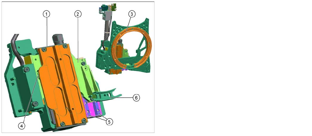
Legend
1. Z motor, primary part
2. Z motor, secondary part
3. Raceway
4. Support roller
5. Linear guidance Z axis
6. Snap jaws