00194614-08 Trainingsdoku. SG X-Serie_X4i SW70x (AL2)_EN.pdf - 第334页
TwinHead Description of Boards on the TwinHe ad Settings Student Guide SIPLACE X-Serie and X4I SW70x (AL2) 334 P&P Head Main Board 9.4.1.4 P&P Head Main Board P&P head main board [00352 833-xx] Legend The mai…
TwinHead
Settings Description of Boards on the TwinHead
333 Student Guide SIPLACE X-Serie and X4I SW70x (AL2)
Description of LEDs H2-H9
The voltage monitors trigger as soon as the target voltage is exceeded or undershot by 5%.
Base Ada pter for TwinHead (SX1/2 s eries)
9.4.1.3 Base Adapter for TwinHead (SX1/2 series)
The Base Adapter PCB (Part Number 03055517-xx) has the same purpose as the Head Adapter that is
used on the X series machines. If head modularity is performed and the TwinHead exchanged for
another head type, then the Base Adapter PCB must also be exchanged.
Legend
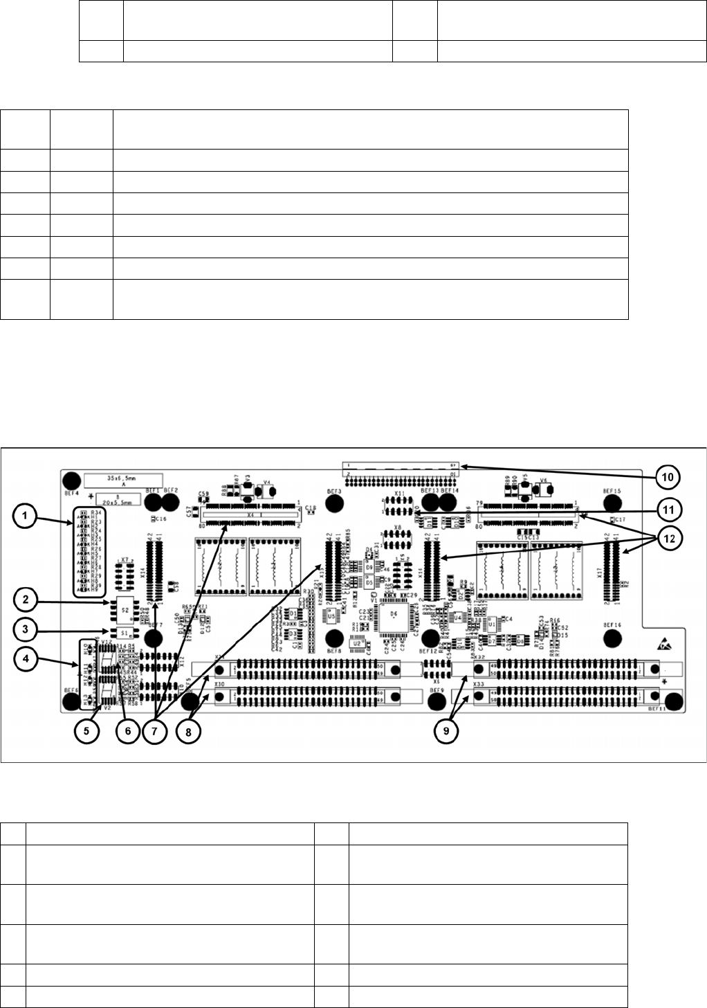
4 X6 Programming connector for FPGA 9 X30-X31 flat ribbon connection for segment
1
5 X9, X16, X17 Connector for HCU2
H2 RS232 Shines when the programming connector for the HCU is connected, see DIP switch
setting at the head interface.
H3 1V5 Voltage monitor 1.5 V, shines red in event of errors.
H4 3V3 Voltage monitor 3.3 V, shines red in event of errors.
H5 5V Voltage monitor 5 V, shines red in event of errors.
H6 15V Voltage monitor 15 V, shines red in event of errors.
H7 DP Voltage monitor DP (currently without function)
H8 24V Voltage monitor 24 V, shines red in event of errors.
H9 LOC Voltage monitor local, shines red as soon as one of the voltage monitors triggers (not
for 24 V)
1 LED H1-H9 7 X4-X14-X15 connector for HCU 1
2 DIP switch S2 (4 pin) 8 X30-X31 connector for ribbon cable segment
1
3 DIP switch S1 (2 pin) 9 X32-X33 connector for ribbon cable segment
2
4 LED H10-H13 10 X3 connector to the gantry interface board
C700
5 7 segment display V2 11 X11 Service connector for checking voltages
6 7-segment display V12 12 X9-X16-X17 connector for HCU2
TwinHead
Description of Boards on the TwinHead Settings
Student Guide SIPLACE X-Serie and X4I SW70x (AL2) 334
P&P Head Main Board
9.4.1.4 P&P Head Main Board
P&P head main board [00352833-xx]
Legend
The main board is mounted directly on the P&P head. This board is connected to the head adapter or
the base adapter via two flat ribbon cables.
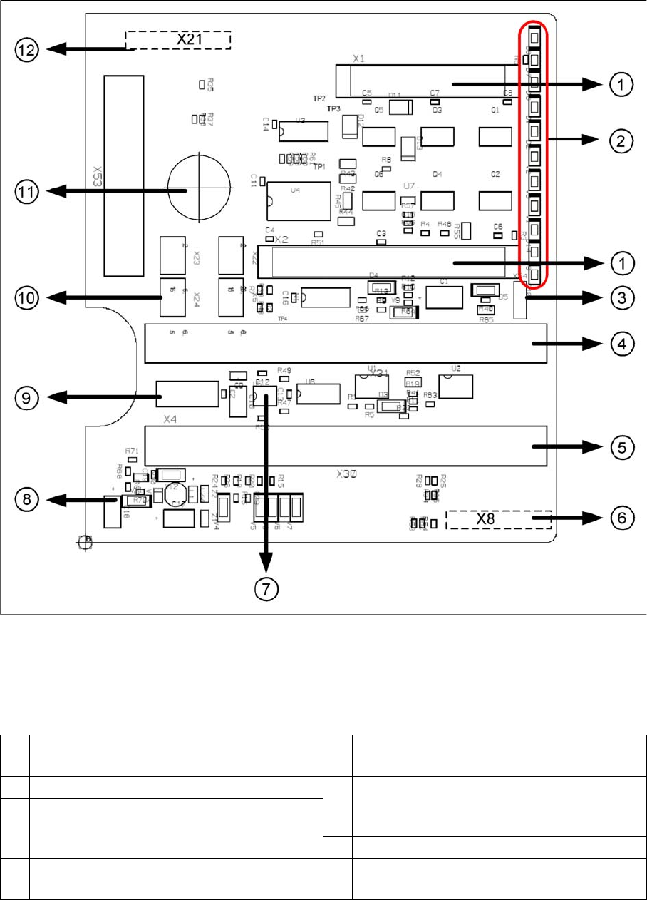
1 2 connectors for the 16 bit CAN Bus processor
(not used)
7 EEPROM stores the head specific data (head
exchange, reference run)
2 LEDs (see below) 8 Power supply 15 V for the Track signals D-
Axis (at the moment deactivated via the
jumper X54)
3 X54 Jumper currently set to ON with the new
force measurement board set to OFF (see
LED V2/V_SP)
9 X4 Connector track signals Z axis
4 Connector to the head adapter flat ribbon
cable
10 Connector pneumatic valve (retract unit)
TwinHead
Settings Description of Boards on the TwinHead
335 Student Guide SIPLACE X-Serie and X4I SW70x (AL2)
To (2) LEDs (description sequence downwards):
Vision Control Board for IC Camera or FC Ca mera
9.4.1.5 Vision Control Board for IC Camera or FC Camera
The vision control board is installed in sector 2 and sector 4 for the stationary cameras.
5 Connector to the head adapter flat ribbon
cable
11 Hole for pneumatic pipe to the vacuum
generator
6 X8: Flex-Cable (Signals: Track signals D-
Axis, Power supply Z Axis/D-Axis, Z
Temperature and, SPI Bus)
12 X21 Connector for vacuum generator
LED Color Description
D8 Green Off – retract unit is moved out – LED shines briefly
D7 KLEMM Green On - display showing that the return cylinder has been projected
downwards.
D6 BERO Green Off - without function (previously: proximity switch Z axis up)
D1 DRUCK Yellow Off - without function (Z pressure)
D2 KLEMM Yellow On – clamping Z axis
Off – retract unit is at top position
V2/V_SP Green Shows the voltage supply 15 V for the D-axis track signals.
Off – at jumper setting ON and old force measurement board.
On – TwinHeads with new force measurement board have the 15V
regulated on the main board i.e. the jumper must be set to OFF and the
LED will be on.
V3 15V_ Green On – 15 V for the D-axis track signals
V1 TEMP Green On - Z axis motor temperature is OK
D14 ALARM Red Off – alarm output for vacuum generator
On – vacuum generator defect
D9 DRUCK Green Off - without function (Z pressure)
D10 24V+ Green On – 24 V for vacuum generator is OK
NOTICE
When using stationary camera ≧ version 04, the Vision control board is integrated into the
cameras. The Vision control board no longer applies in the sectors as well as on newer X
machines and SX machines.