00194614-08 Trainingsdoku. SG X-Serie_X4i SW70x (AL2)_EN.pdf - 第200页
Gantry Checking the Track Signals Track Signals and Zero Pulse Student Guide SIPLACE X-Serie and X4I SW70x (AL2) 200 X24 on X Axis Head Interface X24 on X Axis Head Interface Checking th e Track Sign als 6.4.2 Checking t…
Gantry
Track Signals and Zero Pulse Checking the Zero Pulse Signal
199 Student Guide SIPLACE X-Serie and X4I SW70x (AL2)
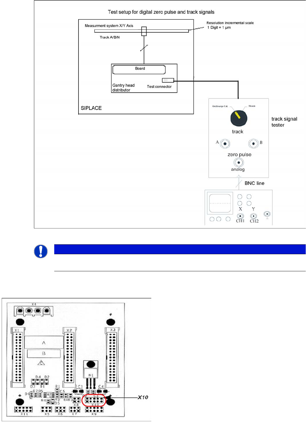
Measurement procedure for checking the digital zero pulse signal and the digital track signals.
X10 on Y Axis Gantry Interfa ce
X10 on Y Axis Gantry Interface
NOTICE
The procedure for measuring the digital zero pulse is identical to that for measuring the analog
zero pulse.
Connector assignment X10:
1. Pin 1 Ground
2. Pin 2 Track A
3. Pin 3 Track A\
(A\ means inverted A)
4. Pin 4 Ground
5. Pin 5 Track B
6. Pin 6 Track B\
7. Pin 7 +5V
8. Pin 8 Track N
9. Pin 9 Track N\
10. Pin 10 Key
Gantry
Checking the Track Signals Track Signals and Zero Pulse
Student Guide SIPLACE X-Serie and X4I SW70x (AL2) 200
X24 on X Axis Head Interface
X24 on X Axis Head Interface
Checking the Track Signals
6.4.2 Checking the Track Signals
Analog Track Signals
6.4.2.1 Analog Track Signals
To check the track signals, connect the track signal tester and the oscilloscope. (see "6.4.1.1 Measuring
the Analog Zero Pulse Signal" [ ➙ 197])
► Switch the machine on.
► Switch the track signal tester to Calibrate oscilloscope.
► Switch the oscilloscope to DC, Refr., Non Store, Auto (20 ms).
► Voltages V/Division decrease up to 0.5 V/Div.
► Switch the oscilloscope to X/Y --> Illuminated point will appear!
► Move the point into the middle of the display.
► Measurement system to position Sinus amplifier output.
► Manually move the selected axis back and forth.
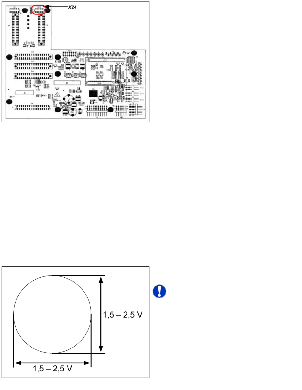
Connector assignment X24:
1. Pin 1 Ground
2. Pin 2 Track A
3. Pin 3 Track A\
4. Pin 4 Ground
5. Pin 5 Track B
6. Pin 6 Track B\
7. Pin 7 +5V
8. Pin 8 Track N
9. Pin 9 Track N\
10. Pin 10 Key
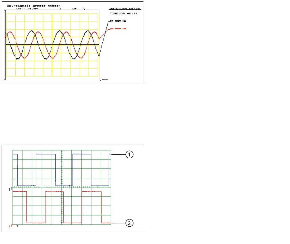
Analog track signals A and B in X/Y oscilloscope mode
► The adjacent picture should appear on the
oscilloscope.
NOTICE! A new version of the incremental
encoder (one field lens) can recognize signals from 1.8 to
3.6 Vss.
Gantry
Track Signals and Zero Pulse Checking the Track Signals
201 Student Guide SIPLACE X-Serie and X4I SW70x (AL2)
Digital T rack Signals
6.4.2.2 Digital Track Signals
To check the digital track signals, connect the track signal tester and the oscilloscope. (see "6.4.1.2
Measuring the Digital Zero Pulse Signal" [ ➙ 198])
The measurement sequence is identical to that described in "6.4.2.1 Analog Track Signals" [ ➙ 200].
Analog track signals 90° phase shift
► Switch the oscilloscope to normal operation.
► The adjacent picture should appear on the
oscilloscope.
Digital track signals 90° phase shift
Legend
1. Track A
2. Track B