00194614-08 Trainingsdoku. SG X-Serie_X4i SW70x (AL2)_EN.pdf - 第251页
C&P20A Settings Boar d Descriptions for C&P20A 251 Student Guide SIPLACE X-Serie and X4I SW70x (AL2) Head interface C700X on SX4 ma chines Legend 1 X15 To signal generator X14 Test connector track signals 7 LEDs …
C&P20A
Board Descriptions for C&P20A Settings
Student Guide SIPLACE X-Serie and X4I SW70x (AL2) 250
The voltage monitors trigger as soon as the target voltage is exceeded or undershot by 5%.
Head Int erface o n SX4 Machines with HCU
7.5.1.3 Head Interface on SX4 Machines with HCU
The head interface on the SIPLACE SX4 is available in two versions due to the mirrored gantries.
▪ Head interface C700X-L [03055067-xx) for gantry 1 and 3
▪ Head interface C700X-R [03055069-xx] for gantry 2 and 4
Both versions have the same functions, connectors and switches.
The head interface is supplied with a voltage of 40 V via the trailing cable. Further voltages for the
electronics and other subsystems are supplied via a DC/CD converter.
Further voltages and signals are:
▪ Track signals X axis
▪ Temperature sensor
▪ FDB bus / CAN bus
▪ Voltages for the star axis, Z axis and X axis are provided by the power supply and distributed to the
head interface.
H7 DP Voltage monitor DP (currently without function)
H8 24V Voltage monitor 24 V, shines red in event of errors
H9 LOC Voltage monitor local - shines red as soon as one of the voltage monitors
triggers (not for 24 V)
C&P20A
Settings Board Descriptions for C&P20A
251 Student Guide SIPLACE X-Serie and X4I SW70x (AL2)
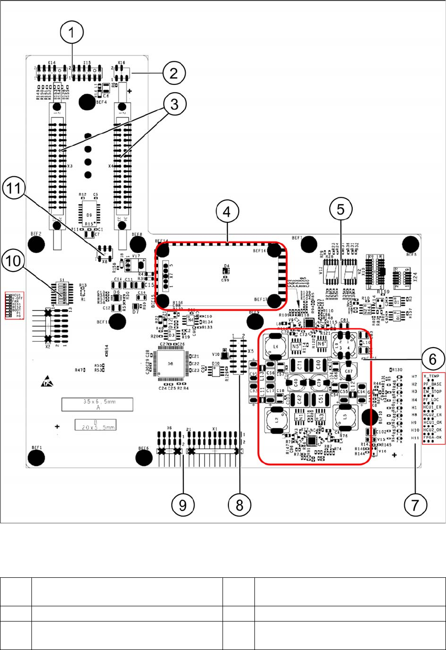
Head interface C700X on SX4 machines
Legend
1 X15 To signal generator
X14 Test connector track signals
7 LEDs H1-H4, H7-H11
2 X16 From temperature sensor X motor 8 X5 From vision board (CAN_H/L)
3 X3-X4 Flat ribbon cables from gantry
interface
9 X1 Test connector, X6 Programming
connector for FPGA
C&P20A
Board Descriptions for C&P20A Settings
Student Guide SIPLACE X-Serie and X4I SW70x (AL2) 252
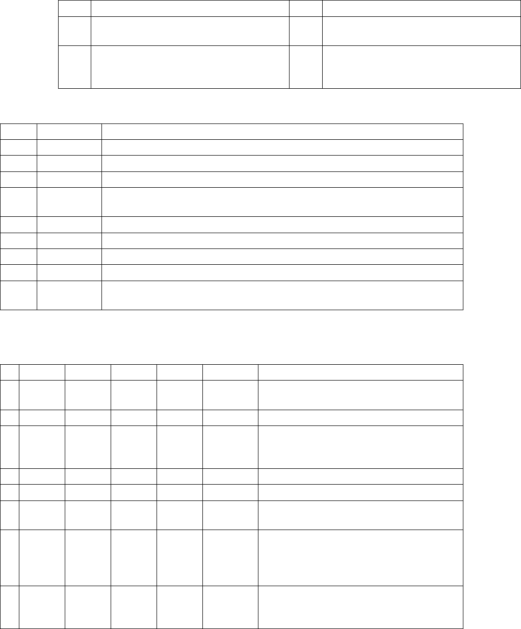
Meaning of LEDs H1 - H11
The voltage monitors trigger as soon as the target voltage is exceeded or undershot by 5%.
Head interface DIP switch S1
4 Power cube X7 24V (input 42V) 10 DIP switch block S1
5 7-segment display
HCU 1 (V12) and HCU2 (TWIN Seg.2 – V2)
11 X8 Fan connector (optional)
6 DC/DC converter +15 V, -15 V, +5 V,
+3.3 V, +1.5 V (input 24 V from power
cube)
LED
H7 X_TEMP X motor temperature monitoring, red temp. too high
H2 PF_BASE Power fail from power supply
H3 EM_STOP Emergency stop shines when cover (hood) is open, emergency stop activation
H4 PF_LOC Power fail local, voltage monitoring of the generated voltages from the DC/DC
converter +15V,-15V,+5V,+3.3V,+1.5V
H1 HCU1_ER Status display of eSW application 1
H8 HCU2_ER Status display of eSW application 1
H9 HCU1_OK Status display of eSW application 1
H10 HCU2_OK Status display of eSW application 1
H11 FPGA_OK Field Programmable Gate Array. Monitors the micro controller on the C700X ->
should always be green
S Gantry 1 Gantry 2 Gantry 3 Gantry 4
1 0 1 0 1 Gantry ID
0
2 0 0 1 1 Gantry ID1
3 0 0 0 0 Boot HCU can be set to bootstrap mode; RES1 to
ON; BOOT to ON; RES1 OFF; BIOS
download via external interface possible
4 0 0 0 0 RES1 Reset HCU1
5 0 0 0 0 RES2 Reset HCU2
6 0 0 0 0 FAN Switch for activating or deactivating the fan
(optional) on X
7 0 0 0 0 V-OFF DC/DC converter default "OFF", when
switched to "ON" preventing a run-up of the
voltages after switching on the machine (for
test purposes only)
8 0 0 0 0 HCU Selector switch in bootstrap mode via
external interface "ON" - HCU 2 and "OFF" -
HCU 1