00194614-08 Trainingsdoku. SG X-Serie_X4i SW70x (AL2)_EN.pdf - 第52页
Overview Pneumatic Unit Overview of Components Student Guide SIPLACE X-Serie and X4I SW70x (AL2) 52 Overview of V oltages in the Power Supply Unit 3.2.1.1 Overview of Voltages in the Power Supply Unit Pneuma tic Uni t 3.…
Overview
Overview of Components Power supply
51 Student Guide SIPLACE X-Serie and X4I SW70x (AL2)
Overview of Com ponents
3.2 Overview of Components
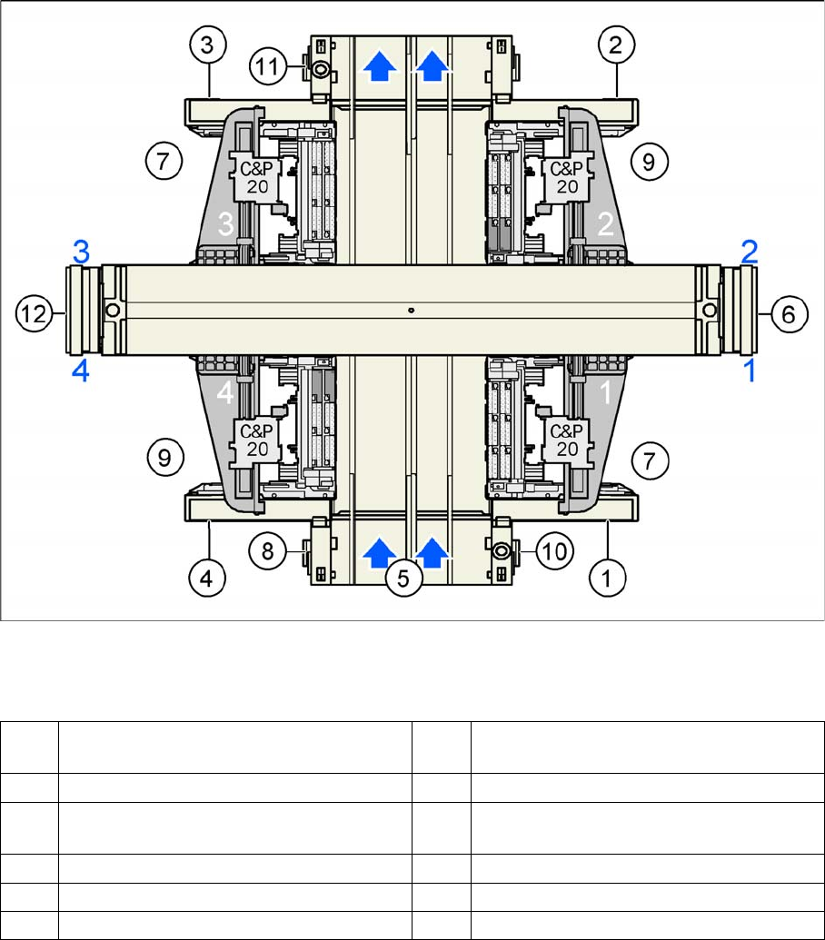
SIPLACE X4I - top view
Legend
Power supply
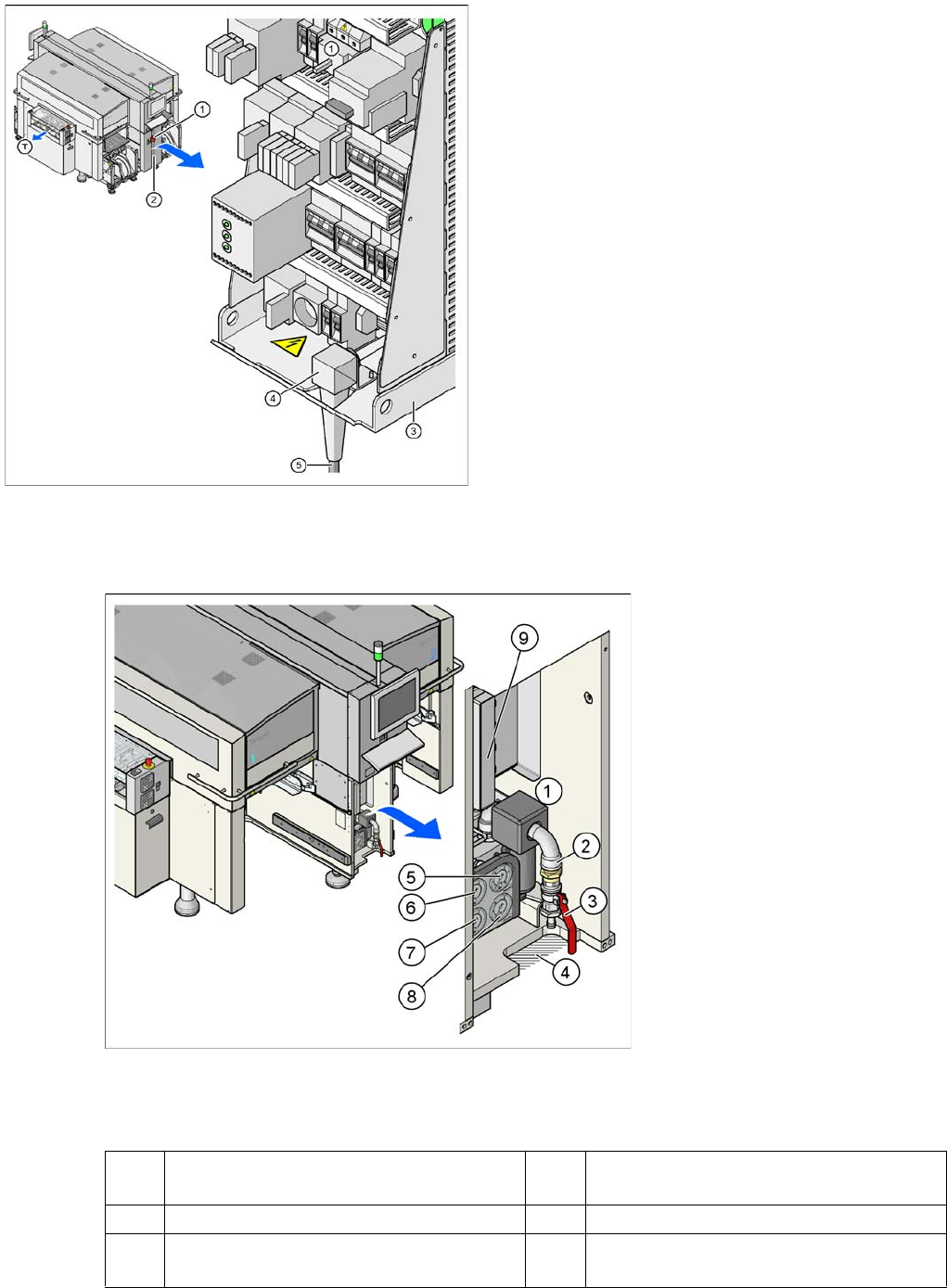
3.2.1 Power supply
The main power supply unit is mounted on a compact rack unit and is located on the left in the middle
section of the machine. From outside, you can only see the red main switch.
A lockable door prevents access to the power supply.
1 Sector 1 7 Location for component table 40 tracks,
each with 8 mm X feeder
2 Sector 2 (main distributor) 8 Computer unit
3 Sector 3 9 Location for component table 34 tracks,
each with 8 mm X feeder
4 Sector 4 (subdistributor) 10 Axis unit placement area 1 (PA1)
5 Transport direction 11 Axis unit placement area 2 (PA2)
6 Pneumatic unit & conveyor control 12 Power supply unit
Overview
Pneumatic Unit Overview of Components
Student Guide SIPLACE X-Serie and X4I SW70x (AL2) 52
Overview of V oltages in the Power Supply Unit
3.2.1.1 Overview of Voltages in the Power Supply Unit
Pneumatic Unit
3.2.2 Pneumatic Unit
Pneumatic unit as rack unit
Legend
Power supply
Legend
1. Main switch
2. Cover on the power supply unit
3. Power supply unit
4. Bracket for the cable fixture
5. Mains connection cable
T = PCB transport direction
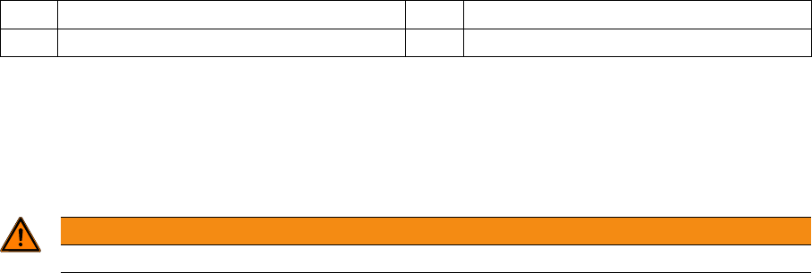
1 Pneumatic Unit 6 Manometer for bulkcase or nozzle changer
DLM
2 Compressed air hose coupling 7 Manometer for gantries
3 Shutoff valve 8 Manometer for machine components
(docking unit, conveyor, cutter, NC C&P20)
Overview
Overview of Components Pneumatic Unit
53 Student Guide SIPLACE X-Serie and X4I SW70x (AL2)
The pneumatic unit is mounted on a compact rack unit and is located on the right in the middle section
of the machine. Unauthorized access to the unit is prevented by a locked door, which can be opened
with a machine key. The pneumatic unit includes all electrical connections for control/regulation of the
compressed air supply and the conveyor control. The conveyor control with the SMEMA (Siemens)
board interface is responsible for the transport of boards in the machine and for the transport from the
upstream and downstream station.
Pneumatic Circuit For Cooling the Y Linear Motors in Placement Areas 1/2
3.2.2.1 Pneumatic Circuit For Cooling the Y Linear Motors in Placement Areas 1/2
An additional pneumatic circuit, supplied with ambient air, has been integrated to cool the Y linear
motors. The ambient air is sucked in via a filter, with the help of a fan motor and is distributed to the Y
motors. The compressed air then escapes through the sides of the Y motors.
Pneumatic Circuit For Cooling the X Linear Motors in Placement Areas 1/2
3.2.2.2 Pneumatic Circuit For Cooling the X Linear Motors in Placement Areas 1/2
The X motors are cooled by the discharged air from the vacuum generator of the C&P20A head.
Compresse d Air Distrib utor Block
3.2.2.3 Compressed Air Distributor Block
The pneumatic unit is used to prepare and distribute the compressed air required in the machine. The
inlet pressure at the compressed air connection must be at least 5.0 bar.
The following pneumatic circuits are supplied with compressed air via the distributor block:
▪ Gantries 1 - 4 (placement heads), vacuum generation: 5.0 bar
▪ Conveyor system: 5.0 bar
▪ Tape cutter for locations 1 - 4: 5.0 bar
▪ Nozzle changer for locations 1 - 4: 5.0 bar
▪ Feed-in units for the changeover tables: 5.0 bar
▪ Bulkcase feeder for locations 1 - 4: 2.5 bar
Fine adjustment for the individual pneumatic circuits is performed directly at the pneumatic units, via the
adjustment valves.
4 Gap for compressed air hose 9 Conveyor control TSP301
5 Manometer for input pressure
WARNING
NEVER disconnect compressed air lines while they are still pressurized. Risk of injury!