00194614-08 Trainingsdoku. SG X-Serie_X4i SW70x (AL2)_EN.pdf - 第130页
Communication and Control Function Control and Troubleshooting for Service Work One Wire Bus Student Guide SIPLACE X-Serie and X4I SW70x (AL2) 130 Allocation o f Subsystems to the Hardware Components Allocation of Subsys…
Communication and Control
One Wire Bus Function Control and Troubleshooting for Service Work
129 Student Guide SIPLACE X-Serie and X4I SW70x (AL2)
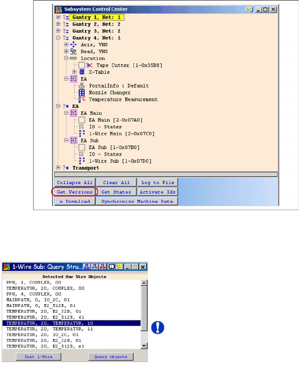
Subsystem control
▪Select Get Versions.
All available subsystems will be shown with their firmware versions and their CAN ID.
▪ Doubleclick on the IO SUB (PA1) directory to open the 1 wire subdirectory. The following dialog will
appear:
One wire sub query structure with example of X4I
► Select Query objectsand all subsystems on the
one wire bus at PA 1 will be displayed.
► The function Init 1-Wire is not required, as the
one wire bus system is initialized when the machine
is switched on. One wire bus initialization is required
for test purposes or in cases of errors e.g. after
disconnecting a node.
NOTICE! The next pages show the assignment
of the lines from the adjacent window for the relevant
hardware components of the one wire bus (HF/HF3, X
series, X4I)
Query Structure

Communication and Control
Function Control and Troubleshooting for Service Work One Wire Bus
Student Guide SIPLACE X-Serie and X4I SW70x (AL2) 130
Allocation o f Subsystems to the Hardware Components
Allocation of Subsystems to the Hardware Components
Assignme nt HF/HF3 PA1
Assignment HF/HF3 PA1
SIPLACE HF/HF3 - PA1
Subsystem Hardware components Comments
Temperature, 1, coupler, 00 PCB: 1 wire trailing
interface
Trailing interface gantry 1
Temperature, 4, coupler, 00 PCB: 1 wire trailing
interface
Trailing interface gantry 4
NC, 4, coupler, 00 1 wire hub for NC Hub for NC at location 4 for NC row 1/2
NC, 1, coupler, 00 1 wire hub for NC Hub for NC at location 1 for NC row 1/2
Mainpath, 0, IO_2C, 01
Mainpath, 0, E2_512B, 01
I/O submodule I/O module, the-1-Wire-CAT5 board
interface will be integrated later into the
I/O module
Temperature, 1, E2_512B, 81
Temperature, 1, E2_32B, 01
Temperature, 1, E2_512B, 61
Temperature, 1, temperature, 10
Temperature, 1, temperature, 11
Temperature, 1, IO_2C,01
Temperature sensors
Gantry 1
The two temperature sensors form a unit
and can only be replaced as a set. The
gantry recognition part can not be
replaced.
Temperature, 4, E2_512B, 81
Temperature, 4, E2_32B, 01
Temperature, 4, E2_512B, 61
Temperature, 4, temperature, 10
Temperature, 4, temperature, 11
Temperature, 4, IO_2C,01
Temperature sensors
Gantry 4
The two temperature sensors form a unit
and can only be replaced as a set. The
gantry recognition part can not be
replaced.
NC, 4, E2 32B, 81
NC, 4, AD, 03
NC, 4, AD, 15
NC, 4, AD, 16
1 wire hub NC on location
4
Shows, that the 1 wire hub is connected.
NC, 4, E2_32, 01
NC, 4, AD, 01
NC, 4, IO_8C, 01
Control board in NC
Gantry 4, only for
C&P20A NC
Control board of NC row 1
(only for C&P20A NC).
NC, 4, E2_32, 02
NC, 4, AD, 02
NC, 4, IO_8C, 02
Control board in NC
Gantry 4, only for
C&P20A NC
Control board of NC row 2
(only for C&P20A NC).
NC, 1, E2_32B, 81
NC, 1, AD, 03
NC, 1, AD, 15
NC, 1, AD, 16
1 wire hub NC on location
1
Shows that the 1 wire hub is connected.
NC, 1, E2_32B, 01
NC, 1, AD, 01
NC, 1, IO_8C, 01
Control board in NC
Gantry 1, only for
C&P20A NC
Control board of NC row 1
(only for C&P20A NC).
NC, 1, E2_32B, 02
NC, 1, AD, 02
NC, 1, IO_8C, 02
Control board in NC
Gantry 1, only for
C&P20A NC
Control board of NC row 2
(only for C&P20A NC).

Communication and Control
One Wire Bus Function Control and Troubleshooting for Service Work
131 Student Guide SIPLACE X-Serie and X4I SW70x (AL2)
Assignment X Series (up to S W 60x) PA1
Assignment X Series (up to SW 60x) PA1
SIPLACE X-series - PA1
Assignment X4I and X Series (from SW 70x) PA1
Assignment X4I and X Series (from SW 70x) PA1
SIPLACE X4I - PA1
Subsystem Hardware components Comments
NC, 1, coupler, 00 1-Wire CAT5 interface
on the I/O module
Temperature, 20, coupler, 00 1-Wire CAT5 interface
on the I/O module
NC, 4, coupler, 00 1-Wire CAT5 interface
on the I/O module
Mainpath, 0, IO_2C, 01
Mainpath, 0, E2_512B, 01
1-Wire CAT5 interface
on the I/O module
1-Wire-CAT5 board interface will be
integrated later into the I/O module
Temperature, 20, E2_32B, 01
temperature, 20, E2_512B, 61
Temperature, 20, temperature, 10
Temperature, 20, temperature, 11
Temperature, 1, IO_2C,01
Temperature sensors
Gantry 1
The two temperature sensors form a unit
and can only be replaced as a set. The
gantry recognition part can not be
replaced.
Temperature, 20, E2_32B, 81
Temperature, 20, E2_512B, e1
Temperature, 20, temperature, 90
Temperature, 20, temperature, 91
Temperature, 20, IO_2C,81
Temperature sensors
gantry 4
The two temperature sensors form a unit
and can only be replaced as a set. The
gantry recognition part can not be
replaced.
NC, 4, AD, 03
NC, 4, AD, 01
NC, 4, AD, 81
1 wire hub NC on
location 4
Shows, that the 1 wire hub is connected.
NC, 4, E2_32B, 01
NC, 4, IO_8C, 01
NC, 4, AD, 01
Control board in NC
Gantry 4, only for
C&P20A NC
Control board of NC row 1
(only for C&P20A NC).
NC, 4, E2_32B, 81
NC, 4, IO_8C, 81
NC, 4, AD, 97
Control board in NC
Gantry 4, only for
C&P20A NC
Control board of NC row 2
(only for C&P20A NC).
NC, 1, AD, 01
NC, 1, AD, 03
NC, 1, AD, 81
1 wire hub NC on
location 1
Shows, that the 1 wire hub is connected.
NC, 1, E2_32B, 01
NC, 1, IO_8C, 01
NC,1 AD, 15
Control board in NC
Gantry 1, only for
C&P20A NC
Control board of NC row 1
(only for C&P20A NC).
NC, 1, E2_32B, 81
NC, 1, IO_8C, 81
NC, 1, AD, 97
Control board in NC
Gantry 1, only for
C&P20A NC
Control board of NC row 2
(only for C&P20A NC).
Subsystem Hardware components Comments
NC, 1, coupler, 00 1-Wire CAT5 interface
on the I/O module
Not needed, as the NC operates with
CAN nodes.
Temperature, 20, coupler, 00 1-Wire CAT5 interface
on the I/O module
NC, 4, coupler, 00 1-Wire CAT5 interface
on the I/O module
Not needed, as the NC operates with
CAN nodes.