00194614-08 Trainingsdoku. SG X-Serie_X4i SW70x (AL2)_EN.pdf - 第128页
Communication and Control Function Control and Troubleshooting for Service Work One Wire Bus Student Guide SIPLACE X-Serie and X4I SW70x (AL2) 128 Function Cont rol and Troubleshooting fo r Service Wor k 4.5.2 Function C…
Communication and Control
One Wire Bus One Wire Bus - Structure
127 Student Guide SIPLACE X-Serie and X4I SW70x (AL2)
Legend:
See also
4.3.10.1 DIP Switch on Main and Subdistributor (for Version -03) [ ➙ 107]
One Wir e CAT5 G antry Boar d
One Wire CAT5 Gantry Board
Tempera ture Sen sors and Gantry Rec ognition (EEPROM )
Temperature Sensors and Gantry Recognition (EEPROM)
1 MA / PC switch must be set to MA
(machine)
LED 1 NC 1/3
2 Switch must be set to V2 LED 2 Temperature sensors
3 Interface 1-Wire CAT5 LED 3 NC 4/2
4 Connector CAT5 cable LED 4 Green "OK"
5 CAN Bus interface to the machine LED 5 Green "Error"
6 CAN Bus Interface to I/O module
NOTICE
In version 03, this board is integrated into the I/O module and settings are made with the DIL
switch of the I/O module.
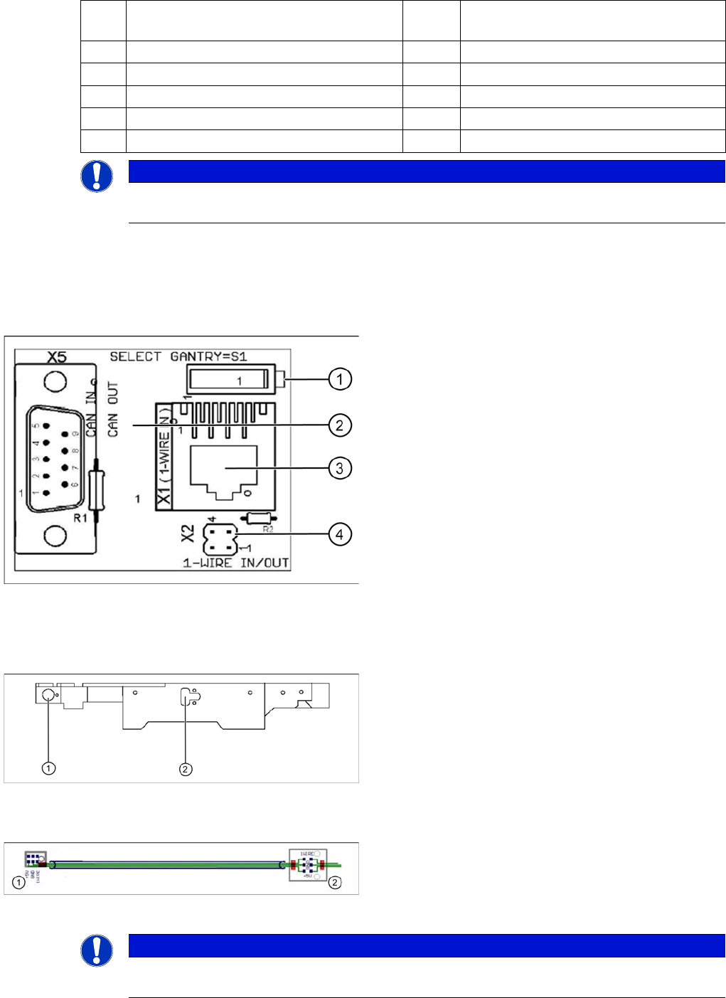
One wire gantry board [03042214-01]
1 wire CAT 5 Gantry on the trailing interface (board
between CAN bus and trailing interface)
Legend:
1. Switches:
Position down = gantry 1/2,
position up = gantry 3/4
2. This board is located directly on the CAN bus
connector of the trailing interface.
3. Connector CAT5 cable direct from the 1 wire CAT5
interface
4. Connection to the second Gantry in the placement
area
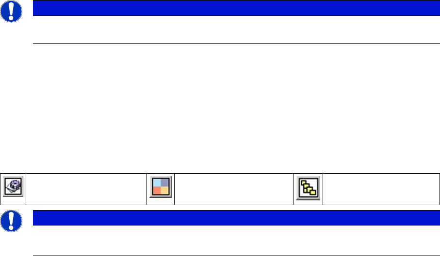
Position of temperature sensors on the head assembly
plate (assembly side of placement head)
1 set of temperature sensors (replacement only as a set)
Legend
1. Temperature sensor on the PCB camera
2. Temperature sensor/ EEPROM gantry recognition
Temperature sensors / gantry recognition
Legend
1. Temperature sensor on the PCB camera
2. Temperature sensor/ EEPROM gantry recognition
NOTICE
The temperature sensors are directly connected to the connector X20 or X21 on the head
interface C500. Either one of these connectors can be used.
Communication and Control
Function Control and Troubleshooting for Service Work One Wire Bus
Student Guide SIPLACE X-Serie and X4I SW70x (AL2) 128
Function Cont rol and Troubleshooting fo r Service Wor k
4.5.2 Function Control and Troubleshooting for Service Work
This section provides an overview of how to assign the one wire bus subsystems to the relevant
hardware assemblies, enabling a structured approach to service work.
With the help of the Cacciatool, all subsystems on the one wire bus can be checked.
Subsystem Query i n PA1
4.5.2.1 Subsystem Query in PA1
▪ Connect the service laptop to the machine CAN bus at PA1.
Make sure that the cable to channel 1 is connected to PA 1 and that the transceiver is connected to
channel 2 of the Kvaser Card or switch off the query for the transceiver at channel 2 in the Change
Properties .
▪ Start the Caccia software and check the machine configuration and the language set in Caccia.
▪ This can be opened by double-clicking on the Subsystem control center.
NOTICE
All the CAN bus commands listed in this section are also equally applicable for the SIPLACE
X4I, even if the NC and the reject bin are no longer controlled or monitored by the one wire bus.
Change Properties Change Machine
Configuration
Open Subsystem Control
Center
NOTICE
Caccia
CACCIA is only fully supported in English. Functions may be missing in the other languages.
Communication and Control
One Wire Bus Function Control and Troubleshooting for Service Work
129 Student Guide SIPLACE X-Serie and X4I SW70x (AL2)
Subsystem control
▪Select Get Versions.
All available subsystems will be shown with their firmware versions and their CAN ID.
▪ Doubleclick on the IO SUB (PA1) directory to open the 1 wire subdirectory. The following dialog will
appear:
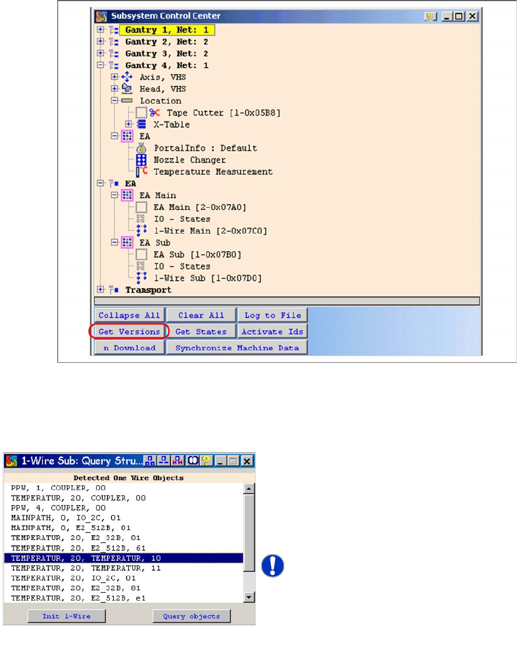
One wire sub query structure with example of X4I
► Select Query objectsand all subsystems on the
one wire bus at PA 1 will be displayed.
► The function Init 1-Wire is not required, as the
one wire bus system is initialized when the machine
is switched on. One wire bus initialization is required
for test purposes or in cases of errors e.g. after
disconnecting a node.
NOTICE! The next pages show the assignment
of the lines from the adjacent window for the relevant
hardware components of the one wire bus (HF/HF3, X
series, X4I)
Query Structure