00194614-08 Trainingsdoku. SG X-Serie_X4i SW70x (AL2)_EN.pdf - 第253页
C&P20A Settings Boar d Descriptions for C&P20A 253 Student Guide SIPLACE X-Serie and X4I SW70x (AL2) Base Ada pter for CPx head s (for SX 1/2) 7.5.1.4 Base Adapter for CPx heads (for SX1/2) The Base Adapter PCB (…
C&P20A
Board Descriptions for C&P20A Settings
Student Guide SIPLACE X-Serie and X4I SW70x (AL2) 252
Meaning of LEDs H1 - H11
The voltage monitors trigger as soon as the target voltage is exceeded or undershot by 5%.
Head interface DIP switch S1
4 Power cube X7 24V (input 42V) 10 DIP switch block S1
5 7-segment display
HCU 1 (V12) and HCU2 (TWIN Seg.2 – V2)
11 X8 Fan connector (optional)
6 DC/DC converter +15 V, -15 V, +5 V,
+3.3 V, +1.5 V (input 24 V from power
cube)
LED
H7 X_TEMP X motor temperature monitoring, red temp. too high
H2 PF_BASE Power fail from power supply
H3 EM_STOP Emergency stop shines when cover (hood) is open, emergency stop activation
H4 PF_LOC Power fail local, voltage monitoring of the generated voltages from the DC/DC
converter +15V,-15V,+5V,+3.3V,+1.5V
H1 HCU1_ER Status display of eSW application 1
H8 HCU2_ER Status display of eSW application 1
H9 HCU1_OK Status display of eSW application 1
H10 HCU2_OK Status display of eSW application 1
H11 FPGA_OK Field Programmable Gate Array. Monitors the micro controller on the C700X ->
should always be green
S Gantry 1 Gantry 2 Gantry 3 Gantry 4
1 0 1 0 1 Gantry ID
0
2 0 0 1 1 Gantry ID1
3 0 0 0 0 Boot HCU can be set to bootstrap mode; RES1 to
ON; BOOT to ON; RES1 OFF; BIOS
download via external interface possible
4 0 0 0 0 RES1 Reset HCU1
5 0 0 0 0 RES2 Reset HCU2
6 0 0 0 0 FAN Switch for activating or deactivating the fan
(optional) on X
7 0 0 0 0 V-OFF DC/DC converter default "OFF", when
switched to "ON" preventing a run-up of the
voltages after switching on the machine (for
test purposes only)
8 0 0 0 0 HCU Selector switch in bootstrap mode via
external interface "ON" - HCU 2 and "OFF" -
HCU 1
C&P20A
Settings Board Descriptions for C&P20A
253 Student Guide SIPLACE X-Serie and X4I SW70x (AL2)
Base Ada pter for CPx head s (for SX 1/2)
7.5.1.4 Base Adapter for CPx heads (for SX1/2)
The Base Adapter PCB (Part Number 03055516-xx) has the same purpose as the Head Adapter that is
used on the X series machines. It is used on the SX machines with both the CP20 and CPP heads.
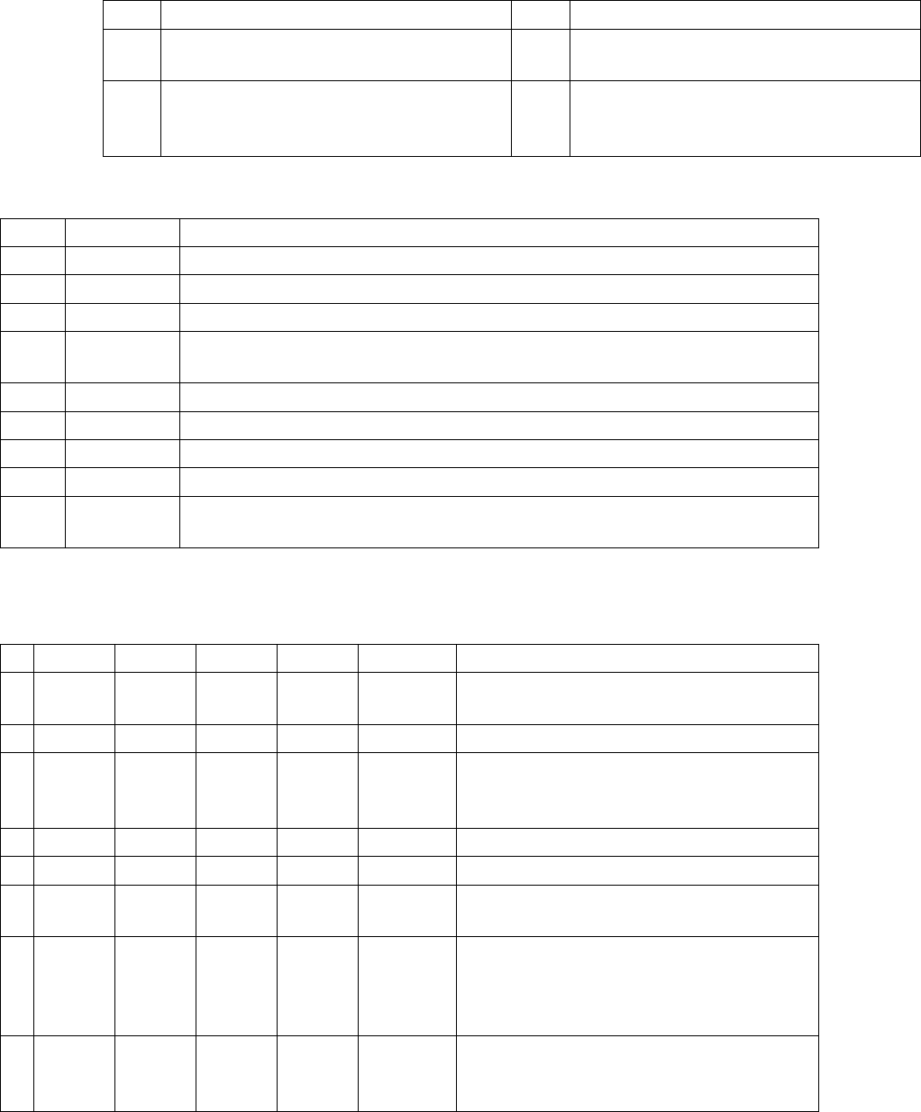
1. Switch S1
2. H1 – H2 (Head)
3. H3 – H9 (Power Failure)
4. H10 – H11 (HCU)
5. 7 segment display
6. DIP switch block S2.
7. X4 - X14 – X15 connectors for the HCU.
8. X1 – X2 ribbon cables to the head.
9. X8 Service connector for checking voltages
10. X3 connector to the head interface C700.
Arrangem ent of Intermedia te Distri butors for C&P20A
7.5.1.5 Arrangement of Intermediate Distributors for C&P20A
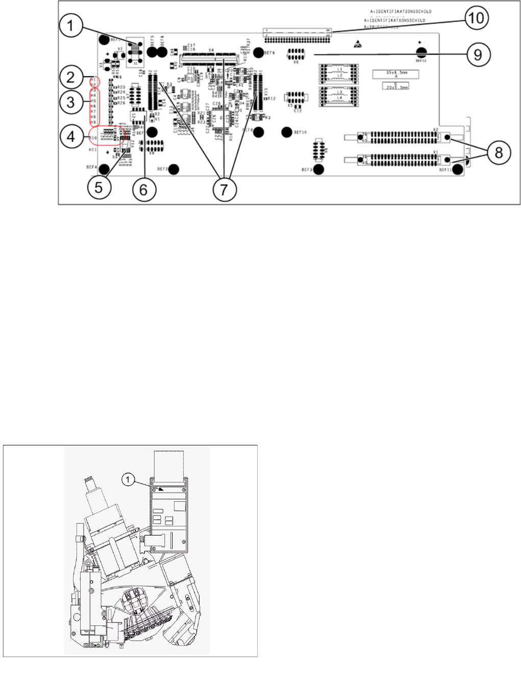
Intermediate distributors for C&P20A
Legend
1. Intermediate distributor board
C&P20A
Board Descriptions for C&P20A Settings
Student Guide SIPLACE X-Serie and X4I SW70x (AL2) 254
Intermediate Distributor - C&P20
Intermediate Distributor - C&P20
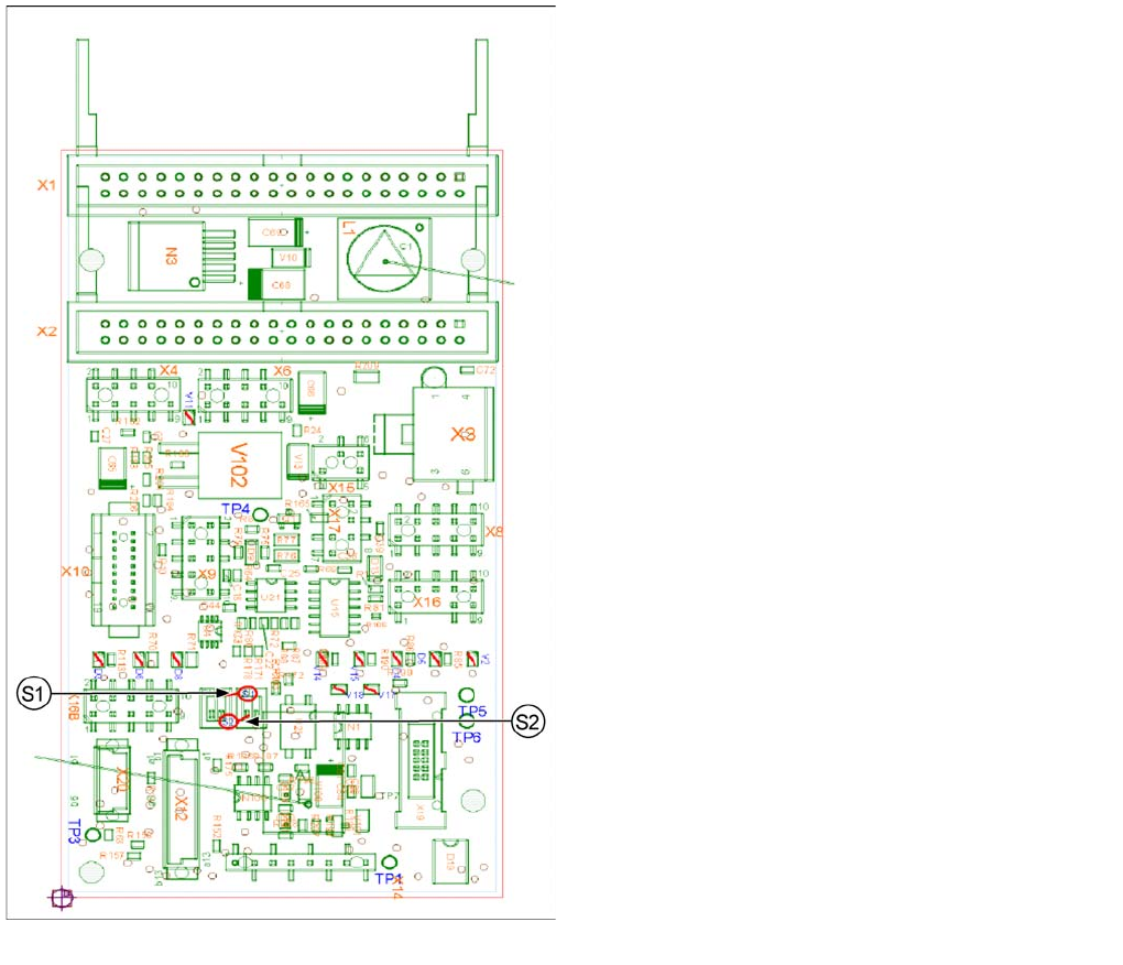
Intermediate distributor - position of the sockets
Legend
The following supply voltages and signals are routed by
the intermediate distributor to the individual placement
head modules or to the head board:
▪ Connector X1, 40 pole: connected with connector X1
on the head adapter board
▪ Connector X2, 40 pole: connected with connector X2
on the head adapter board
▪ Connector X3: connection for the star motor
▪ Connector X4: connection for the star incremental
encoder
▪ Connector X6: connection for the Z axis incremental
encoder
▪ Connector X8: connection for the Z motor
▪ Connector X9: connection for the component sensor
▪ Connector X12: connection for pressure control valve
▪ Connector X14: test connector X14_3: +5 V/X14_4:
+15 V/X14_5: -15 V/X14_7:24 V for DP motors
▪ Connector X15: connection for retract unit
▪ Connector X16: Internal CAN bus C&P20