00194614-08 Trainingsdoku. SG X-Serie_X4i SW70x (AL2)_EN.pdf - 第198页
Gantry Checking the Zero Pulse Signal Track Signals and Zero Pulse Student Guide SIPLACE X-Serie and X4I SW70x (AL2) 198 ► Mo v e t he g a n tr y m an u a l ly o v e r th e z er o p u ls e ( s ee i n s tr u c ti o n s or…
Gantry
Track Signals and Zero Pulse Checking the Zero Pulse Signal
197 Student Guide SIPLACE X-Serie and X4I SW70x (AL2)
Checking the Zero Pulse Signal
6.4.1 Checking the Zero Pulse Signal
The zero pulse must be reliably and clearly recognized by the read head. To ensure this, you can check
both the analog and the digital zero pulse. Electronically controlled settings can not be performed on the
incremental length measurement system.
See also
4.4.1.2 Zero Pulse at the Track Signal Encoder [ ➙ 115]
Measuring the Analog Zero P ulse Signal
6.4.1.1 Measuring the Analog Zero Pulse Signal
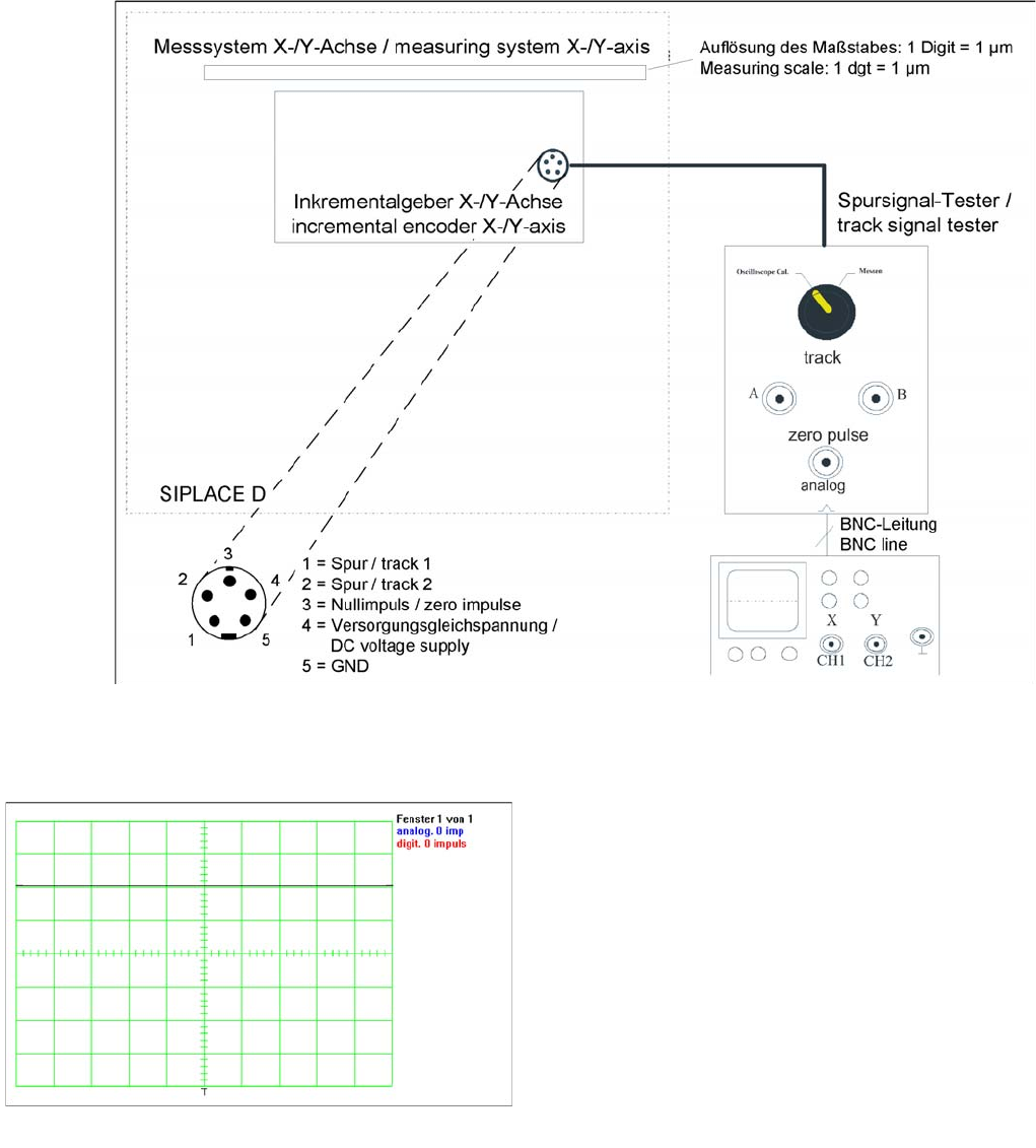
Measurement procedure for checking the analog zero pulse and the analog track signals
Measurem ent Procedure
Measurement Procedure
Measuring the initial zero pulse position
► Connect the measurement tester to the incremental
encoder.
► Main switch ON
► Connect the oscilloscope to the measurement tester.
► Set the measurement adapter to Calibrate
oscilloscope and position the signal at the top,
center of the screen.
Gantry
Checking the Zero Pulse Signal Track Signals and Zero Pulse
Student Guide SIPLACE X-Serie and X4I SW70x (AL2) 198
► Move the gantry manually over the zero pulse (see instructions or description of zero pulse search).
► The following picture should appear on the oscilloscope.
Measuring th e Digital Zer o Pulse Sign al
6.4.1.2 Measuring the Digital Zero Pulse Signal
NOTICE
When the gantry is positioned at the hardware stop, an area of 25mm begins, in which no zero
pulse search is permitted. Check the first zero pulse after this area, on the incremental scale.
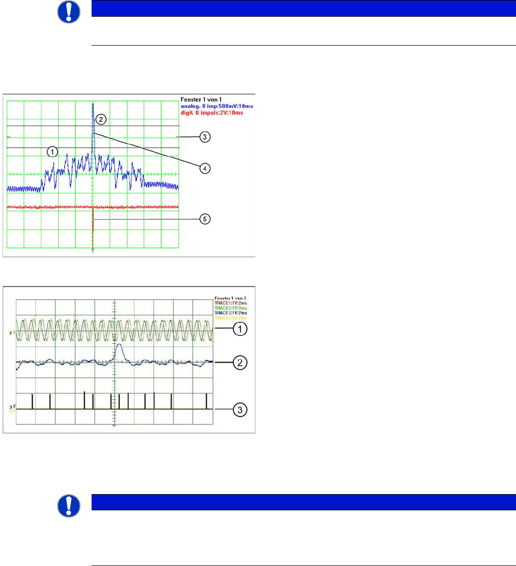
Correctly adjusted read unit
Legend
1. There should be no interference pulse in the
tolerance space of - 0.3 V.
2. The analog zero pulse must overshoot the switching
threshold by more then 0.3V.
3. Initial position
4. Analog zero pulse
5. Digital zero pulse
Incorrectly adjusted read unit or contaminated zero pulse
Legend
1. Analog track signal A and B
2. Analog zero pulse
3. Digital zero pulse
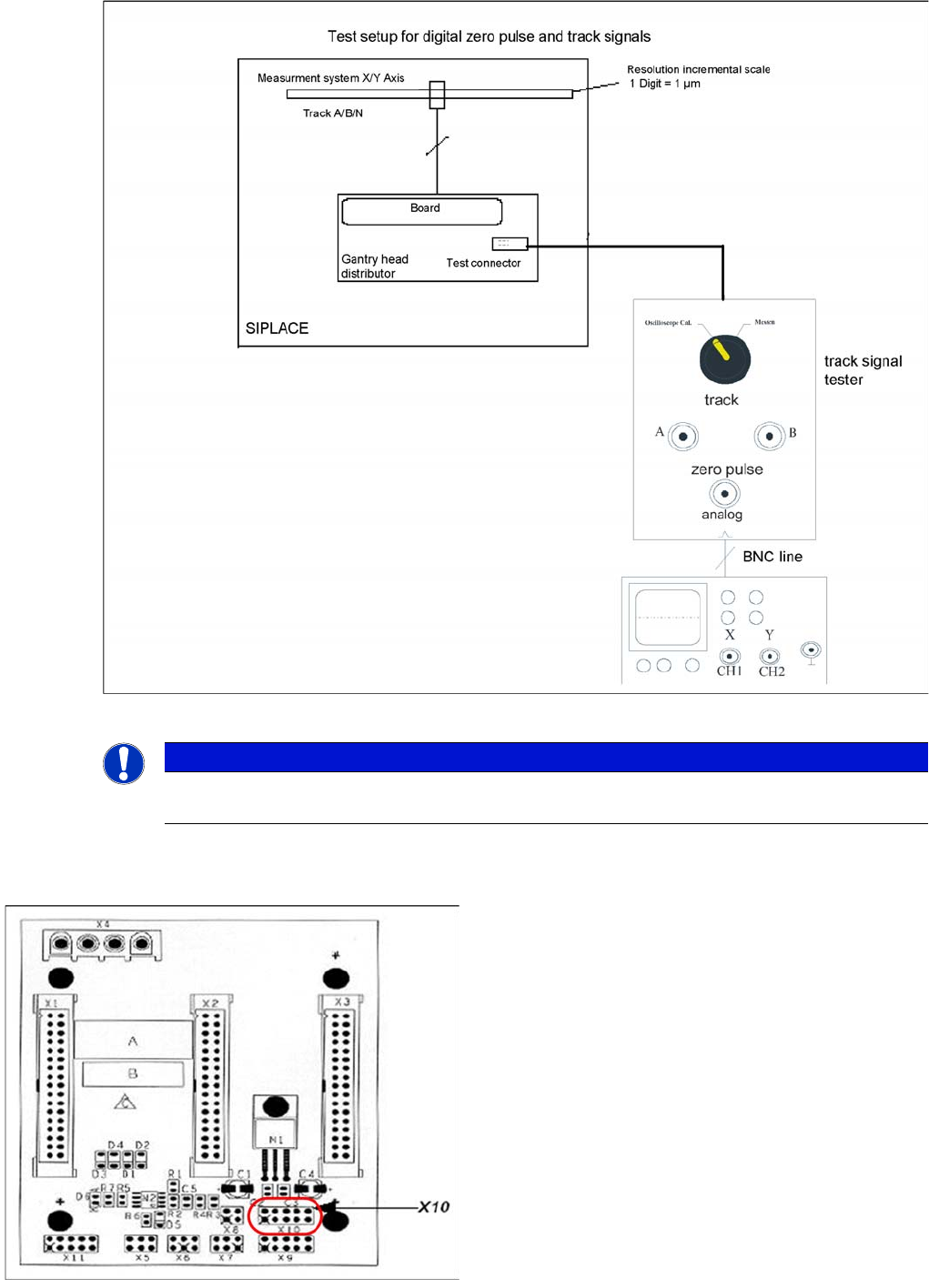
NOTICE
You can also use the BNC socket on the axis test box to check the zero pulse signal (inverted
display of zero pulse signal). The digital signals can be checked (for error location) at
connectors X10 and X24 of the gantry and at the head interface (calculate extra time for Y axes,
dismantling the covers).
Gantry
Track Signals and Zero Pulse Checking the Zero Pulse Signal
199 Student Guide SIPLACE X-Serie and X4I SW70x (AL2)
Measurement procedure for checking the digital zero pulse signal and the digital track signals.
X10 on Y Axis Gantry Interfa ce
X10 on Y Axis Gantry Interface
NOTICE
The procedure for measuring the digital zero pulse is identical to that for measuring the analog
zero pulse.
Connector assignment X10:
1. Pin 1 Ground
2. Pin 2 Track A
3. Pin 3 Track A\
(A\ means inverted A)
4. Pin 4 Ground
5. Pin 5 Track B
6. Pin 6 Track B\
7. Pin 7 +5V
8. Pin 8 Track N
9. Pin 9 Track N\
10. Pin 10 Key