00194614-08 Trainingsdoku. SG X-Serie_X4i SW70x (AL2)_EN.pdf - 第289页
Collect, Pick and Place Head (CPP) Reference Run CPP Head Height Reference Run 289 Student Guide SIPLACE X-Serie and X4I SW70x (AL2) ▪ The gantr y moves the placeme nt head to th e fixed co nveyor side at height measurem…
Collect, Pick and Place Head (CPP)
DP Axes Reference Run Reference Run CPP Head
Student Guide SIPLACE X-Serie and X4I SW70x (AL2) 288
DP Axes Reference Run
8.3.3 DP Axes Reference Run
▪ In the reference run for the star axis, the DP drives rotate the segments into the 0° position.
▪ The DP drives rotate in a clockwise direction, to the zero pulse of the incremental encoder. After the
zero pulse has been reached, the zero point correction value is loaded. The DP axis continues to
rotate around the zero point correction value and sets the position counter to 0 digits.
Reference run of CPP head finished!
The gantry reference run follows – see Chapter Gantry
Height R eference Run
8.3.4 Height Reference Run
With this function we check the correct fitting of the nozzle on the sleeve and that the correct nozzle type
like the programmed one are set to the sleeves. The nozzle length is taken to calculate the pick up and
placement height for the subsequent placements.
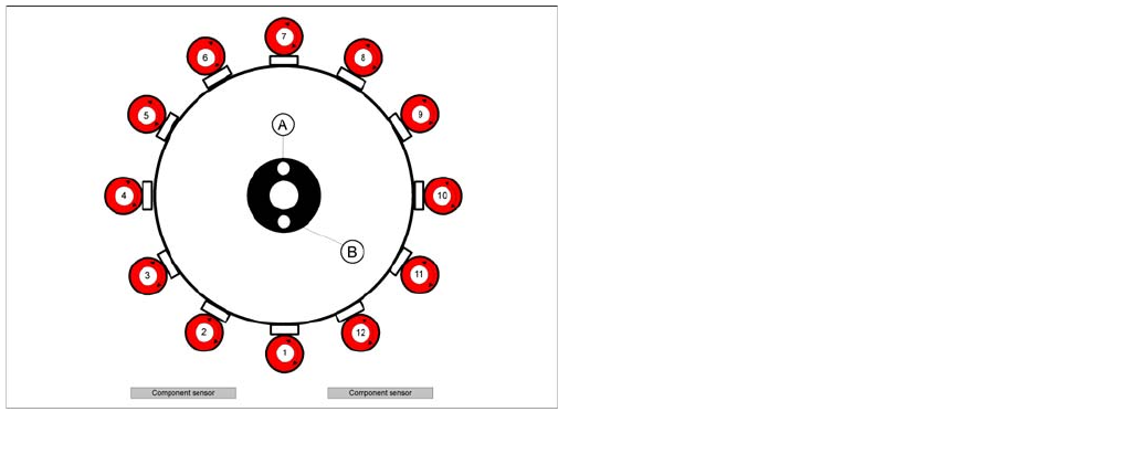
DP axis reference run
Legend
A : Vacuum measurement hold circuit
B : Vacuum measurement placement circuit
The DP axis rotates the nozzle into the correct pickup
angle and placement angle. After component recognition
has been performed, the DP axis turns the components
into the correct placement angles and the determined
correction angle from the vision system.
Collect, Pick and Place Head (CPP)
Reference Run CPP Head Height Reference Run
289 Student Guide SIPLACE X-Serie and X4I SW70x (AL2)
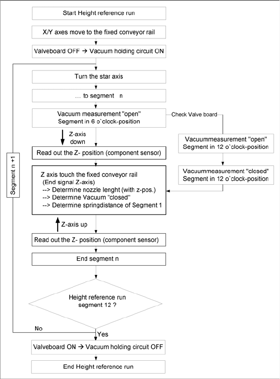
▪ The gantry moves the placement head to the fixed conveyor side at height measurement position.
▪ The star turns the segment for measuring into the pickup/placement position
▪ The value Open vacuum is measured for the relevant segment.
The Z axis is positioned downwards:
▪ When the component sensor beam is interrupted, the Z position of the axis is determined for the
component sensor.
▪ When the Z axis touches the conveyor side, the mechanical nozzle length is determined by the Z
position value and the closed vacuum value is measured.
The Z axis is positioned upwards:
▪ When the component sensor beam is no longer interrupted, the Z position of the axis will be
measured again for the component sensor.
▪ During each star rotation the valve terminal and the holding circuit are checked with open and closed
nozzle in the 12 position.
Collect, Pick and Place Head (CPP)
Determining the Vacuum and Threshold Values Reference Run CPP Head
Student Guide SIPLACE X-Serie and X4I SW70x (AL2) 290
Determining the Vacuum and Threshold Values
8.3.5 Determining the Vacuum and Threshold Values
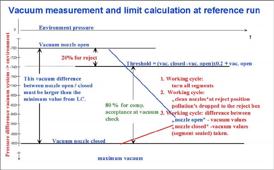
Measuring and calculating the vacuum values for a reference run
▪ The vacuum is measured twice at the reference point: first with open and then with closed nozzle
tips.
▪ The value with closed segment does no longer depend on the ambient pressure it is controlled by
the pressure control valve. The nozzle fit (nozzle pickup error) and the quality (contamination/
damage) of the nozzle tip influence the vacuum measurement values.
▪ The value by open pressure control valve depends on the nozzle size and condition. The smaller the
nozzle, the greater the open valve value will be. This nozzle-specific value is preset by the SIPLACE
Pro computer. A contaminated or blocked nozzle will also give a higher valve.
▪ The difference between the open and closed nozzles has been preset by the programming system
as an ideal case minimum value. This value is different for all nozzle types e.g. 120 mbar for 1004,
1014 nozzles. If these values are not achieved, the error message “Vacuum difference open-closed
is too low” will appear.
▪ The threshold for component acceptance is also set now. Assumed are following values for a 1004
nozzle: a value of 660 mbar when the nozzle is open and a value of 852 mbar when the nozzle is
closed. The calculation is performed as follows:
Vacuum distance = (852 (closed) - 660 (open))= 192 mbar
This is greater than the vacuum distance required in the parameter specifications for this nozzle type
(120 mbar). The open vacuum of 660 mbar is significantly greater than the required 250 mbar.