00194614-08 Trainingsdoku. SG X-Serie_X4i SW70x (AL2)_EN.pdf - 第132页
Communication and Control Function Control and Troubleshooting for Service Work One Wire Bus Student Guide SIPLACE X-Serie and X4I SW70x (AL2) 132 Function Control wi th Caccia 4.5.2.2 Function Control with Caccia Exampl…

Communication and Control
One Wire Bus Function Control and Troubleshooting for Service Work
131 Student Guide SIPLACE X-Serie and X4I SW70x (AL2)
Assignment X Series (up to S W 60x) PA1
Assignment X Series (up to SW 60x) PA1
SIPLACE X-series - PA1
Assignment X4I and X Series (from SW 70x) PA1
Assignment X4I and X Series (from SW 70x) PA1
SIPLACE X4I - PA1
Subsystem Hardware components Comments
NC, 1, coupler, 00 1-Wire CAT5 interface
on the I/O module
Temperature, 20, coupler, 00 1-Wire CAT5 interface
on the I/O module
NC, 4, coupler, 00 1-Wire CAT5 interface
on the I/O module
Mainpath, 0, IO_2C, 01
Mainpath, 0, E2_512B, 01
1-Wire CAT5 interface
on the I/O module
1-Wire-CAT5 board interface will be
integrated later into the I/O module
Temperature, 20, E2_32B, 01
temperature, 20, E2_512B, 61
Temperature, 20, temperature, 10
Temperature, 20, temperature, 11
Temperature, 1, IO_2C,01
Temperature sensors
Gantry 1
The two temperature sensors form a unit
and can only be replaced as a set. The
gantry recognition part can not be
replaced.
Temperature, 20, E2_32B, 81
Temperature, 20, E2_512B, e1
Temperature, 20, temperature, 90
Temperature, 20, temperature, 91
Temperature, 20, IO_2C,81
Temperature sensors
gantry 4
The two temperature sensors form a unit
and can only be replaced as a set. The
gantry recognition part can not be
replaced.
NC, 4, AD, 03
NC, 4, AD, 01
NC, 4, AD, 81
1 wire hub NC on
location 4
Shows, that the 1 wire hub is connected.
NC, 4, E2_32B, 01
NC, 4, IO_8C, 01
NC, 4, AD, 01
Control board in NC
Gantry 4, only for
C&P20A NC
Control board of NC row 1
(only for C&P20A NC).
NC, 4, E2_32B, 81
NC, 4, IO_8C, 81
NC, 4, AD, 97
Control board in NC
Gantry 4, only for
C&P20A NC
Control board of NC row 2
(only for C&P20A NC).
NC, 1, AD, 01
NC, 1, AD, 03
NC, 1, AD, 81
1 wire hub NC on
location 1
Shows, that the 1 wire hub is connected.
NC, 1, E2_32B, 01
NC, 1, IO_8C, 01
NC,1 AD, 15
Control board in NC
Gantry 1, only for
C&P20A NC
Control board of NC row 1
(only for C&P20A NC).
NC, 1, E2_32B, 81
NC, 1, IO_8C, 81
NC, 1, AD, 97
Control board in NC
Gantry 1, only for
C&P20A NC
Control board of NC row 2
(only for C&P20A NC).
Subsystem Hardware components Comments
NC, 1, coupler, 00 1-Wire CAT5 interface
on the I/O module
Not needed, as the NC operates with
CAN nodes.
Temperature, 20, coupler, 00 1-Wire CAT5 interface
on the I/O module
NC, 4, coupler, 00 1-Wire CAT5 interface
on the I/O module
Not needed, as the NC operates with
CAN nodes.
Communication and Control
Function Control and Troubleshooting for Service Work One Wire Bus
Student Guide SIPLACE X-Serie and X4I SW70x (AL2) 132
Function Control with Caccia
4.5.2.2 Function Control with Caccia
Example - nozzle changer (NC)
In addition to the station software, there are also two other means for checking the function of the NC.
NC menu
NC menu
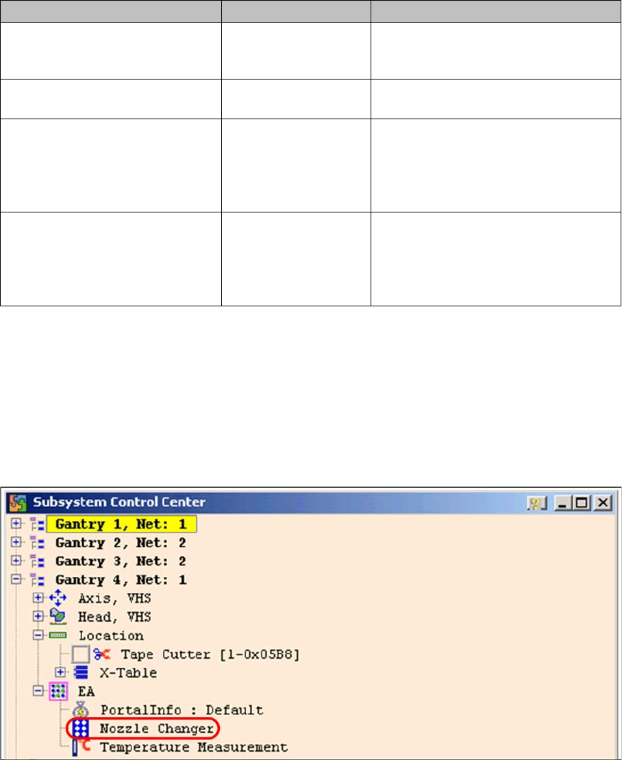
► Open the IO folder for the relevant location in the Subsystem control center.
► Double-click on Nozzle Changer
Subsystem control center (nozzle changer)
► the following menu will appear:
Mainpath, 0, IO_2C, 01
Mainpath, 0, E2_512B, 01
1-Wire CAT5 interface
on the I/O module
1-Wire-CAT5 board interface will be
integrated later into the I/O module
version 03
Temperature, 1, IO_2C,01
Temperature, 20, IO_2C,81
1-Wire CAT5 interface
on the I/O module
Temperature, 20, E2_32B, 01
temperature, 20, E2_512B, 61
Temperature, 20, temperature, 10
Temperature, 20, temperature, 11
Temperature, 1, IO_2C,01
Temperature sensors
Gantry 4
The two temperature sensors form a unit
and can only be replaced as a set. The
gantry recognition part can not be
replaced.
Temperature, 20, E2_32B, 81
Temperature, 20, E2_512B, e1
Temperature, 20, temperature, 90
Temperature, 20, temperature, 91
Temperature, 20, IO_2C,81
Temperature sensors
Gantry 1
The two temperature sensors form a unit
and can only be replaced as a set. The
gantry recognition part can not be
replaced.
Subsystem Hardware components Comments
Communication and Control
One Wire Bus Function Control and Troubleshooting for Service Work
133 Student Guide SIPLACE X-Serie and X4I SW70x (AL2)
Function Control with CAN Bus Commands
Function Control with CAN Bus Commands
Open and close the nozzle changer
➢ Preparation: see subsystem queries.
► Open the network window.
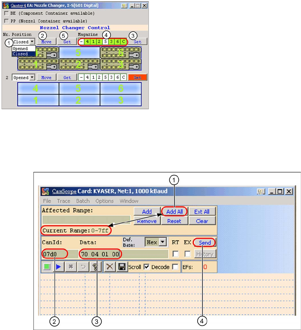
CAN scope NET 1 1 MBaud (network window)
► (1) Select the address range Add All. At Current Range you will see 0-7ff.
► (2) Enter the CAN ID for the relevant CAN bus path.
Placement area 1: 07d0
Placement area 2: 07c0
► (3) Enter the command 70 04 01 00 with spaces
70 --> Move command
04 --> Gantry 4
01 --> NC row 1
00 --> (open NC) / 01 --> closed (close NC)
I/O nozzle changer
Legend
1. Selection window, open/close NC row 1
2. Performs the selected function
3. Status query magazine (micro switch under the
magazine)
4. Status display magazine
5. Status display NC opened / closed