00194614-08 Trainingsdoku. SG X-Serie_X4i SW70x (AL2)_EN.pdf - 第400页
Modular Conveyor Board Clamping Functions Conveyor Settings Student Guide SIPLACE X-Serie and X4I SW70x (AL2) 400 Setting B oard Clamping 11.3.7.1 Setting Board Clamping Setting t he Board Clamping 11.3.7.2 Setting the B…

Modular Conveyor
Conveyor Settings Board Clamping Functions
399 Student Guide SIPLACE X-Serie and X4I SW70x (AL2)
▪ PCB monitoring in the input conveyer, meaning that
if a PCB is recognized in the input conveyer, this PCB will appear on the station GUI and the machine
will close the conveyor interface to the previous station. When using boards with cutouts, the light
barrier signal may extinguish and the interface to the upstream station may be opened although the
board has stopped. Then the next PCB would move into the input conveyer with the PCB still lying
in the input conveyer. The board monitoring function moves the board backwards and then forwards
again, until the light barrier switches.
Board C lamping F unctions
11.3.7 Board Clamping Functions
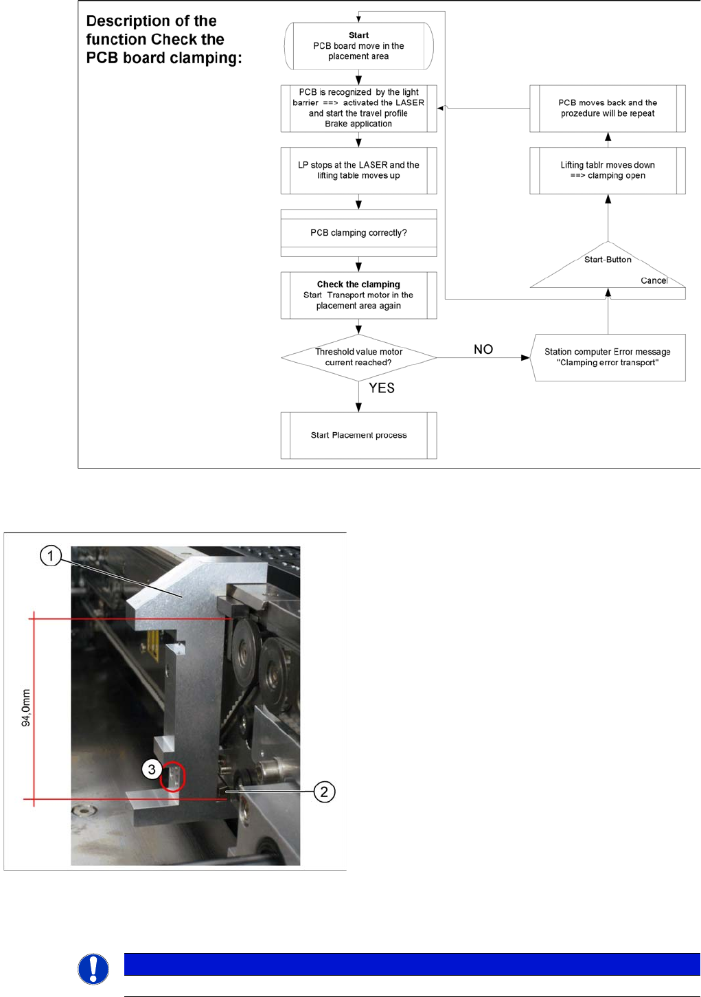
Function description:
▪ The PCB moves into the placement area, it is recognized by the light barrier, stops at the laser and
the lifting table moves up.
▪ Check PCB clamping: The transport motor in the placement area start again. If the PCB is clamped
correctly the motor current will rise up and reach a defined threshold value. Once the board has been
correctly clamped into place, the placement process will begin.
▪ If this threshold is not reached, the system assumes that the board is on its way to the intermediate
or output conveyor and has therefore not been correctly clamped into place.
▪ The station computer will issue the message "PCB not correctly clamped PA1 (PA2)". The process
can be repeated by pressing the "start button".
▪ The lifting table will move downwards, the board will be transported back and the stopper position
will be approached again.
NOTICE
The check whether a PCB is clamping correctly, is controlled with a motor current check of the
transport motor if the PCB board is clamped (Lifting table up). To check the function you could
put a distance plate under the conveyor side edge, so that the lifting table can not move to the
upper position.
The check is not performed if the option "Vacuum Tooling" is installed.
Modular Conveyor
Board Clamping Functions Conveyor Settings
Student Guide SIPLACE X-Serie and X4I SW70x (AL2) 400
Setting B oard Clamping
11.3.7.1 Setting Board Clamping
Setting t he Board Clamping
11.3.7.2 Setting the Board Clamping
Setting actuator
Legend
1. Setting gauge for actuator [03049740-xx]
2. Actuator
3. Drilling, for fixing the actuator screws, when the
gauge is fitted
If the conveyor control issues the error Clamping
error conveyor, you need to check the distance from
the lifting table actuator to the upper edge of the conveyor
belt.
Use the setting gauge to check and adjust the actuator.
The distance from the clamping actuator (lifting table) to
the top edge of the belt should be 94.0 mm at all four
contact points. (see diagram)
NOTICE
This setting should only be made if there are problems with the clamping.
Modular Conveyor
Conveyor Settings Board Clamping Functions
401 Student Guide SIPLACE X-Serie and X4I SW70x (AL2)
► To check whether the board clamping is functioning properly, clamp a board with the lifting table.
Then check whether the board is clamped tightly on the side.
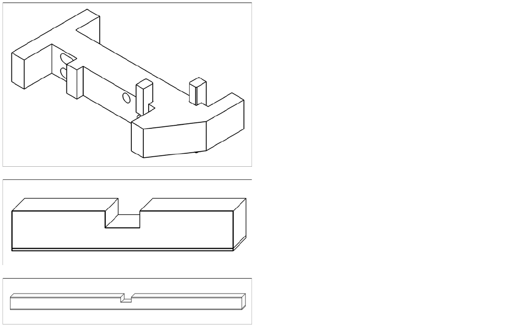
Tools
Setting (single and dual conveyor)
► The terminal strip may need to be modified, depending on the machine type. As the S27 only has a
maximum clamping area of 74 mm, the terminal strip needs to be fitted on the correct side. The
terminal strip for X series, HS-60 and D series machines needs to be set to 94 mm. Fit the terminal
strip accordingly on the gauge.
► The gauge is inserted between the actuator and the clamp.
► The actuator can now be released, moved down and then tightened again through the holes
provided.
Quad lane conveyor settings
► For initial setting, follow the procedure used for the single and dual conveyors (see above). Make
sure that the long terminal strip [03076698-xx] is fitted on the 94 mm side of the "Adjust gauge
actuator cpl.
► As two boards are clamped with the same lifting table, you need to check the clamping play for each
of the single conveyors.
► The clamping actuators are delivered with a basic setting of 94.2 mm to the top edge of the conveyor
belt.
► If problems occur during board clamping (board partially or fully loose), you will need to reset the
clamp.
The cause of this problem is that there are a total of 6 actuators on 3 conveyor edges. If these are
not set accurately enough (they do not form a level), up to 3 actuators might have been set
incorrectly.These then need to be adjusted.
The clamping function is set with the "Adjust gauge
actuator cpl" [03049740-xx].
▪ Terminal strip for S27, HS-60, HF, X2, X3, X4
[03049739-xx]
▪ Long terminal strip for X4I [03076698-xx]