00194614-08 Trainingsdoku. SG X-Serie_X4i SW70x (AL2)_EN.pdf - 第98页
Communication and Control CAN Bus Processor Board C&P Head CAN Bus Student Guide SIPLACE X-Serie and X4I SW70x (AL2) 98 CAN Bus-Co ntrolled F unctions on the C& P20A Head 4.3.4.1 CAN Bus-Controlled Functions on t…
Communication and Control
CAN Bus CAN Bus Processor Board C&P Head
97 Student Guide SIPLACE X-Serie and X4I SW70x (AL2)
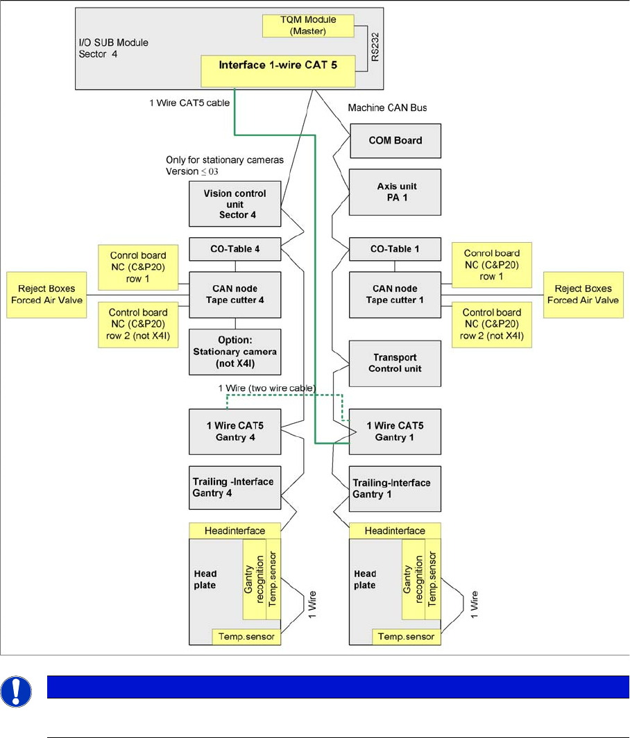
▪ Temperature sensors
▪ Gantry recognition (CFK02, CFK04, CFK06)
One wire overview at an X3 – PA1 with CAN node module
One wire overview at an X3 – PA1 with CAN node module
CAN Bus Processor Bo ard C&P Head
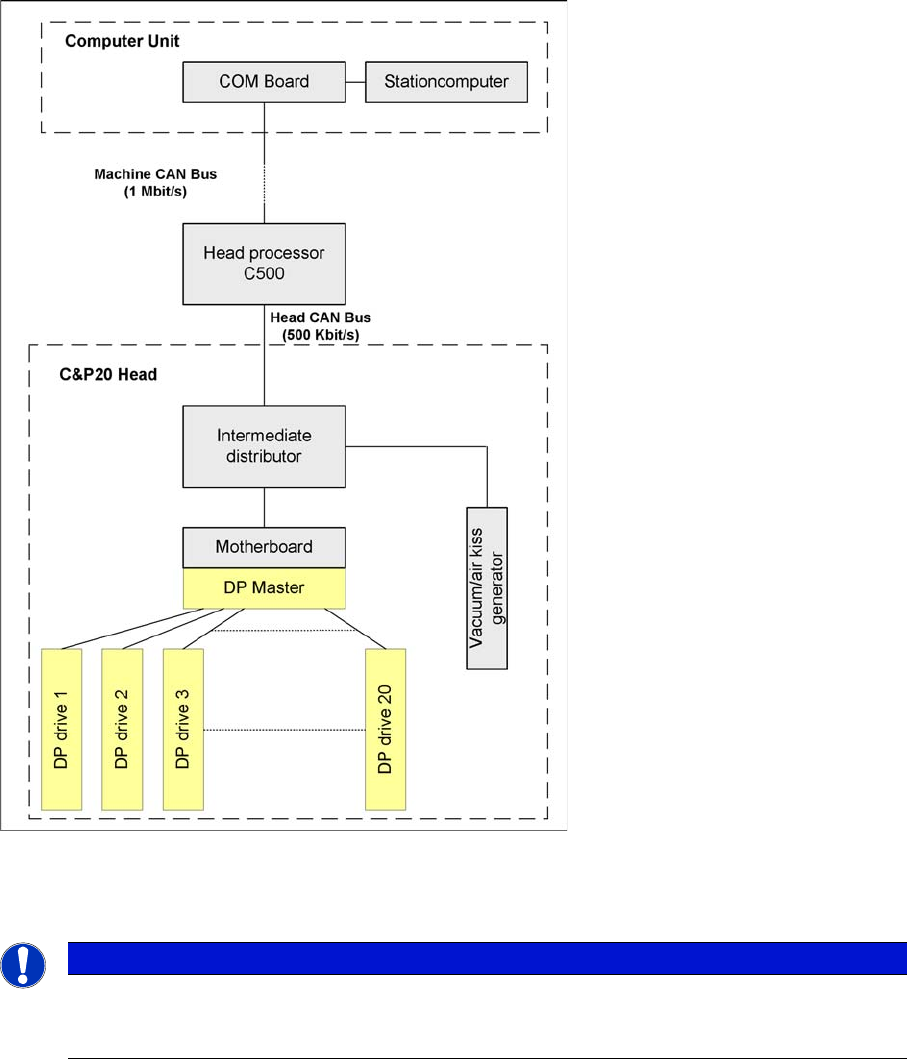
4.3.4 CAN Bus Processor Board C&P Head
Can bus processor board TQM 167 LC is mounted on the head board C500. The processor board is
used at different places in the machine. If the processor board is on the head board, the firmware on the
processor board will control the head-specific actuators and sensors.
NOTICE
After introduction of the CAN node module, the one wire bus is now only needed to check the
temperatures sensors.
Communication and Control
CAN Bus Processor Board C&P Head CAN Bus
Student Guide SIPLACE X-Serie and X4I SW70x (AL2) 98
CAN Bus-Controlled Functions on the C&P20A Head
4.3.4.1 CAN Bus-Controlled Functions on the C&P20A Head
Communication TQM module
The following overview shows various head functions, controlled by the CAN system. Thus, the CAN bus
controls the actuators and sensors of the C&P or CPP head.
NOTICE
The status of the 16 bit processor board is indicated on the 7-segment display.
Normal status on the display is: The dot "." in the display is flashing. (for description see Section
C&P or CPP head).
Communication and Control
CAN Bus CAN Bus Processor Board C&P Head
99 Student Guide SIPLACE X-Serie and X4I SW70x (AL2)
CAN Bus-Controlled Functions on the CPP Head
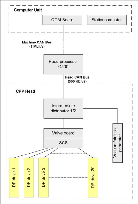
4.3.4.2 CAN Bus-Controlled Functions on the CPP Head
Communication TQM module