00194614-08 Trainingsdoku. SG X-Serie_X4i SW70x (AL2)_EN.pdf - 第281页
Collect, Pick and Place Head (CPP) Overview Overview of Parts 281 Student Guide SIPLACE X-Serie and X4I SW70x (AL2) Cover with H olding Circuit Sensor 8.2.7.15 Cover with Holding Circuit Sensor Legend 1. Rear hea d cover…
Collect, Pick and Place Head (CPP)
Overview of Parts Overview
Student Guide SIPLACE X-Serie and X4I SW70x (AL2) 280
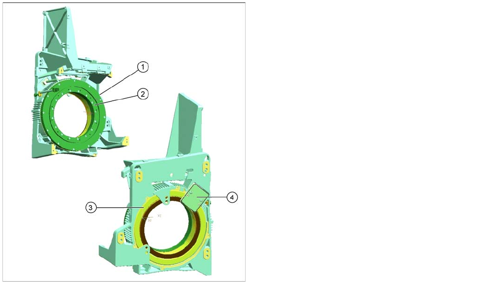
Star motor
8.2.7.14 Star motor
Star Motor Function
Star Motor Function
▪ The star motor is a brushless three-phase drive with sinus commutation.
▪ An optical measurement system is used for both commutation and recognition of the rotary angle.
This supplies the track signals A, B and the zero pulse. The incremental measuring system has
3600 increment lines and one reference fiducial. By a multiplication of 25, 1 digit = 0.004° or
250 digits = 1°.
▪ The motor is controlled with the help of these track signals. The actual position values are evaluated
on the controller assembly of the HCU (A364). The HCU power module (servo card) enhances
performance and is supplied with 2-phase current from the axis controller board. The third phase is
calculated automatically.
▪ The supply line to the star motor has a board with EEPROM, in which the following data is stored:
– Production data (manufacturer, serial number, ...)
– Operating data (errors, travel cycles, ...)
– Machine data (motor data, travel profiles, zero point correction, max. and min. position)
Legend
1. Stator star motor
2. Rotor star motor
Interface for fixing the star frame.
3. Incremental measuring system
4. Read unit incremental measuring system
▪ The star motor is a servo motor, in which the coil is
wound around the stator (1) and the magnets are
taken up by the rotor (2).
▪ The advantage of a torque motor is a much faster
reaction time coupled with a low lift (30° steps). The
motor functions contact free i.e. there is no wear and
tear.
▪ The head casing also serves as the motor casing.
▪ The star motor is not a spare part and can not be
replaced.
Collect, Pick and Place Head (CPP)
Overview Overview of Parts
281 Student Guide SIPLACE X-Serie and X4I SW70x (AL2)
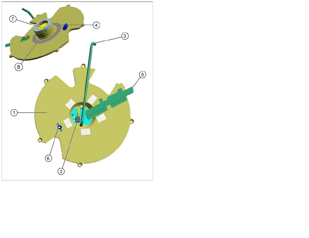
Cover with H olding Circuit Sensor
8.2.7.15 Cover with Holding Circuit Sensor
Legend
1. Rear head cover
The rear cover on the CPP head is fixed to the head
casing with 5 screws. The head therefore needs to be
dismantled from the gantry.
2. Holding circuit sensor
This cover has a board with holding circuit sensor.
This sensor monitors the vacuum in the holding
circuit.
3. Metal tube
This metal tube supplies the pickup/place circuit with
vacuum or air blast from the pressure control valve.
4. Smooth distributor disc
This is located inside the cover. This smooth
distributor disc has two drilled holes. One hole leads
to the pickup and place position. The other hole is
used to measure the vacuum in the holding circuit at
a certain position.
5. Data supply
This consists of a cable for the holding circuit sensor
board and another cable for the power and data
supply to the DP drives, valve terminal and SCS.
6. Centering pin
The centering pin fixes the stationary part of the E/D
transformer (only for CPP heads < Version05).
7. Contact free data transfer (transmitter)
8. Stator for contactless energy transmission (CPP
heads > version 05)
Collect, Pick and Place Head (CPP)
Overview of Parts Overview
Student Guide SIPLACE X-Serie and X4I SW70x (AL2) 282
Intermedia te Distributor
8.2.7.16 Intermediate Distributor
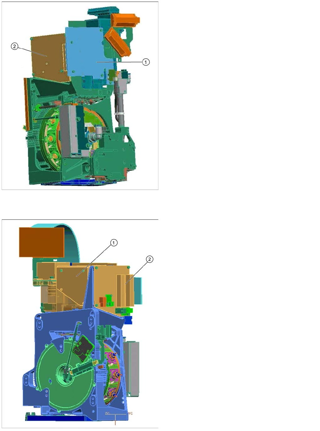
Component camera
8.2.7.17 Component camera
Legend
The intermediate distributor consists of two boards:
1. Intermediate distributor 1 is fitted to the front of the
head.
2. Intermediate distributor 2 is fitted to the left side of the
head.
Functions of the intermediate distributor:
▪ LEDs show the operating voltages at the head and
the state of the sensors
▪ Test connector for the track signals and test pins for
analog signals
▪ Controlled power supply for incremental encoder
from Z and star drive
▪ Interface for component sensor, vacuum unit, holding
circuit vacuum sensor and EEPROM
▪ Startup control for the return cylinder
Legend
1. Component camera
2. Intermediate distributor 2
Component - camera (SST29 / ST38)
The component camera is fitted in the 12.00 position, as
in the case of the C&P6/12 heads.
This camera is responsible for optically recognizing the
component and for calculating its centerpoint.
The component camera evaluates the data determined
and calculates the offset between the component
centerpoint and the nozzle centerpoint plus the angle in
the placement position.