00194614-08 Trainingsdoku. SG X-Serie_X4i SW70x (AL2)_EN.pdf - 第347页
Component Handling Changeover Table Overview 347 Student Guide SIPLACE X-Serie and X4I SW70x (AL2) Component H andling 10 Component Handling Changeover Table 10.1 Changeover Table Overview 10.1.1 Overview This chapt er d…
TwinHead
Nozzle Changer for TwinHead Nozzle changer
Student Guide SIPLACE X-Serie and X4I SW70x (AL2) 346
Position of the nozzle in the magazines
Nozzle Changer for TwinHead
9.5.3 Nozzle Changer for TwinHead
All SIPLACE machines configured with a TwinHead are delivered with a nozzle changer by default. This
nozzle changer can accommodate up to 12 nozzle magazines. There are two types of magazine
available: standard magazines and magazines for special nozzles or grippers. Depending on the
machine type the nozzle changer can be freely configured with magazines. The nozzle changer consists
of a standard module with 3 nozzle garages, for two nozzles each (standard nozzles) and one nozzle
garage for a special nozzle. This configuration can be extended as shown in the diagram below.
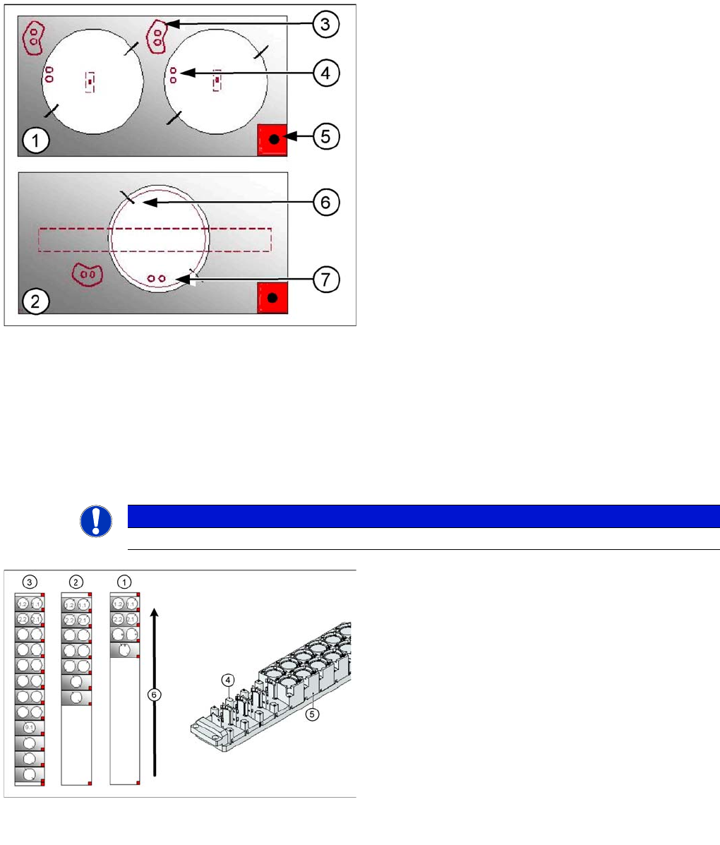
Legend
1. Double magazine for standard nozzles (pickup angle
SW 505 = 184°)
2. Magazine for special nozzles or grippers (pickup
angle SW 505 = 275°)
3. Index pins for correct positioning of nozzles in
magazine
4. Position of nozzle with the holes for the index pins.
5. Calibration fiducial for determining the magazine
position
6. Nozzle centering pins
7. The magazines for the special nozzles are turned by
90° degrees.
NOTICE
The magazines for standard and special nozzles are freely configurable with SW 505 or higher.
Example for a nozzle changer configuration for a
TwinHead
Legend
1. Standard nozzle changer
2. Extended Nozzle changer
3. Complete Nozzle changer
4. Magazine for 1 special nozzle
5. Magazine for 2 standard nozzles
6. Transport direction
Component Handling
Changeover Table Overview
347 Student Guide SIPLACE X-Serie and X4I SW70x (AL2)
Component Handling
10 Component Handling
Changeover Table
10.1 Changeover Table
Overview
10.1.1 Overview
This chapter describes the preparation of components with the changeover tables, the corresponding
docking unit and the pneumatic cutter.
Up to four moveable changeover tables can be docked onto the X machine. The changeover tables are
automatically connected to and disconnected from the docking unit (mechanically and electrically) by
pressing a button. MTC2s can also be used with all X series machines (except X4I).
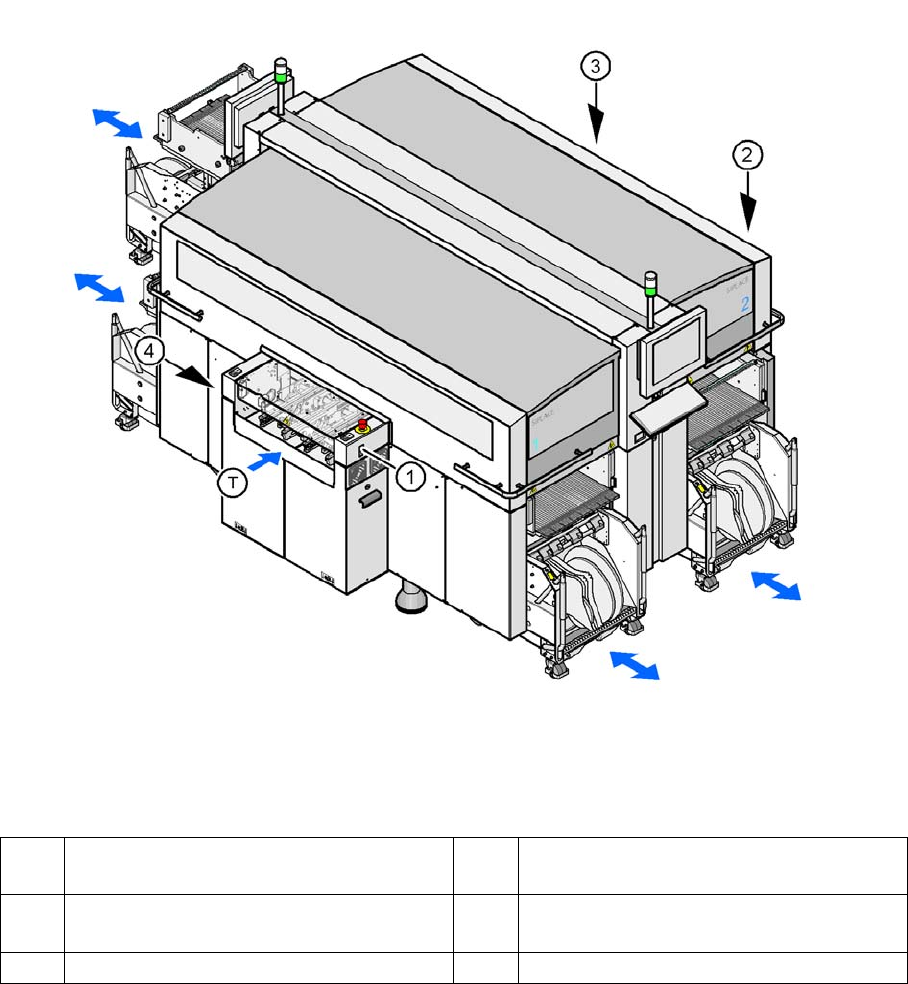
Shows the buttons for docking and undocking the COT‘s
Legend
Changeover Table (X Table)
10.1.1.1 Changeover Table (X Table)
The changeover table and the docking unit form a component supply unit.
1 Button for docking and undocking the
component trolley to location 1
3 Button for docking and undocking the
component trolley to location 3
2 Button for docking and undocking the
component trolley to location 2
4 Button for docking and undocking the
component trolley to location 4
T Direction of board transport
Component Handling
Structure of the Changeover Table (X- Table) Changeover Table
Student Guide SIPLACE X-Serie and X4I SW70x (AL2) 348
Technical Data (X Table):
Technical Data (X Table):
Structure of the Changeover Table (X- Table)
10.1.2 Structure of the Changeover Table (X- Table)
NOTICE
The SIPLACE X4I machine only supports C&P20A heads, X tables and the feeder types 8, 12
and 16 mm.
Feeder capacity 148 tracks width 8mm, 8mm X feeders
74 tracks width 12mm, 12mm X feeders
60 tracks width 16mm, 16mm X feeders tracks width mm.
Feeder locations: 4 changeover tables with integrated waste tape bins
40 locations, each with 8mm X feeders per component trolley at locations 1
and 3
34 locations, each with 8 mm X feeders per component trolley at locations 2
and 4
Feeder types Tape
Interface to the machine Automatic connection to machine during docking (no connection of cables
needed)
Power supply
CAN bus connection
Closing the safety loop
Compressed air connection
Changeover table
heights:
Based on the conveyor height
830 mm ± 15 mm (standard)
900 mm ± 15 mm (SMEMA)
930 mm ± 15 mm (SMEMA)
950 mm ± 15 mm (SMEMA)
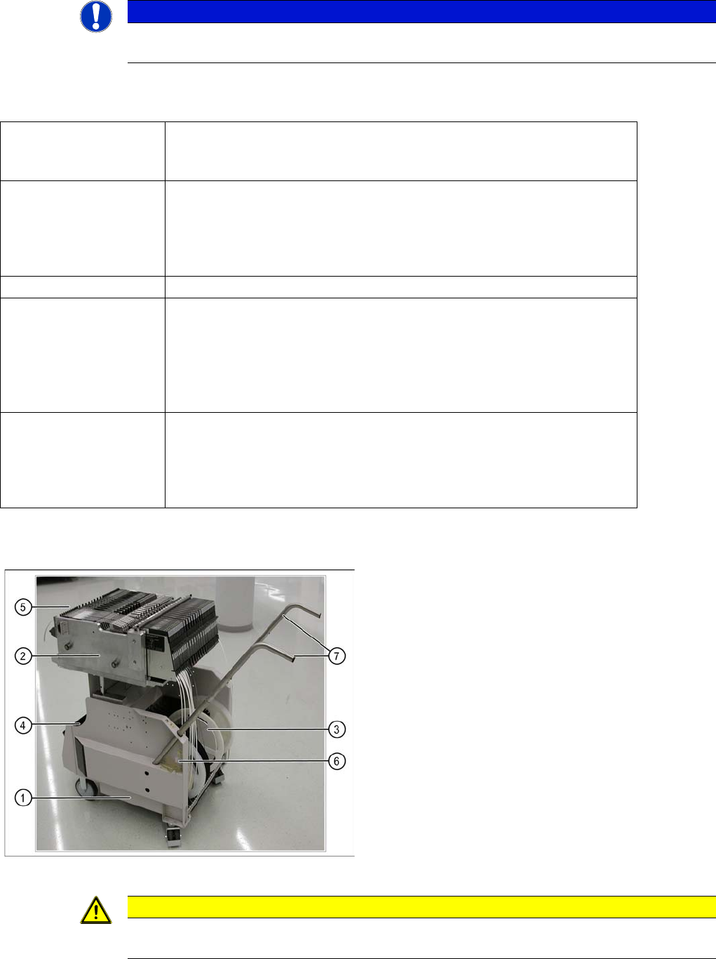
COT (X- table) - side view
Legend
1. Moveable base
2. Changeover table
3. Tape reels container
4. Tape waste bin
5. Interface power supply, communication, safety loop
6. Sticker with an ID number as alphanumeric
characters and as a barcode
7. Handles (can be individually swiveled for model 2)
▪ One pocket can be attached to the side of the
component trolley, for setup list printouts.
CAUTION
Unused locations are to be fitted with dummy feeders to ensure that unauthorized persons do
not reach into the machine.