00194614-08 Trainingsdoku. SG X-Serie_X4i SW70x (AL2)_EN.pdf - 第293页
Collect, Pick and Place Head (CPP) Pickup and Placement Cycle for CPP Placement Modes 293 Student Guide SIPLACE X-Serie and X4I SW70x (AL2) Example 1. Collect and Place mode fo r small components only. 2. Collect and Pla…
Collect, Pick and Place Head (CPP)
Placement Modes Pickup and Placement Cycle for CPP
Student Guide SIPLACE X-Serie and X4I SW70x (AL2) 292
Placement Modes
8.4.2 Placement Modes
The CPP head functions according to the Collect&Place principle, like the C&P12 head, whereby the
additional operating modes Pick&Place and mixed mode help to extend the component spectrum.
The placement mode is, on the one hand, dependent on the configured camera and, on the other hand,
on the component dimensions and their tolerances in SIPLACE Pro.
The respective placement mode is determined by the Optimizer in SIPLACE Pro and can not be
influenced.
Overview of the placement modes
1. Collect & Place Mode
Component Range: 01005-27x27mm, 8,5mm height
Speed: 20.000 to 24.000 cph
Accuracy: +/- 55 µm @ 4 s; 0,3° @ 4s
The Collect-and-Place mode is the same mode for the C&P6/12 and C&P20A placement heads.
Components are picked up (the quantity depends on the number of segments), optically centered with
the component camera and then placed.
1. Mixed Mode
Component Range: 01005-32x32mm, 11,5 mm height
Mixed mode differentiates between the following two cases:
▪ The components are small enough to be rotated by the head.
▪ The components are too large. Just 2 or 3 components are picked up, centered by the stationary
camera and then placed.
1. Pick & Place Mode
Component Range: 01005-50x40mm, 11,5mm height
Speed: up to 1.500 cph
Accuracy: +/- 45 µm @ 4 s; 0,1° @ 4s
P&P mode: The Pick-and-Place mode is the mode used for IC and TwinHead. It is therefore also used
for the CPP head, which picks up components with either one or more segments, according to the
component size. Due to their size, it is not possible to rotate these components with the head and they
need to be optically centered via the stationary camera and then placed.
Collect, Pick and Place Head (CPP)
Pickup and Placement Cycle for CPP Placement Modes
293 Student Guide SIPLACE X-Serie and X4I SW70x (AL2)
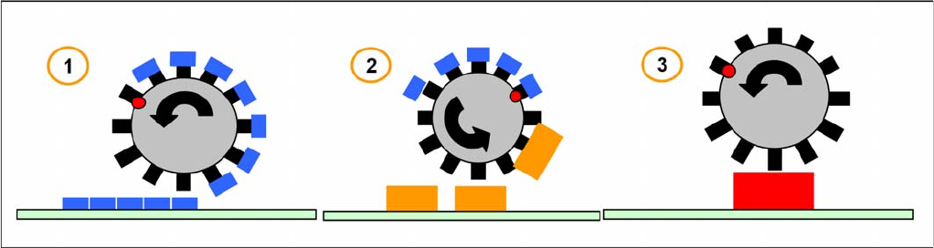
Example
1. Collect and Place mode for small components only.
2. Collect and Place mode (with skipped segments) for medium components.
3. Mixed mode – collect and place for small components, pick and place for high components.
4. Mixed mode – collect and place for small components and pick and place for 1 large component.
The placement mode is dependent on the configured component camera and the component size with
their tolerance in SIPLACE Pro. It is automatically selected by the optimization software.
Collect&Place Mode
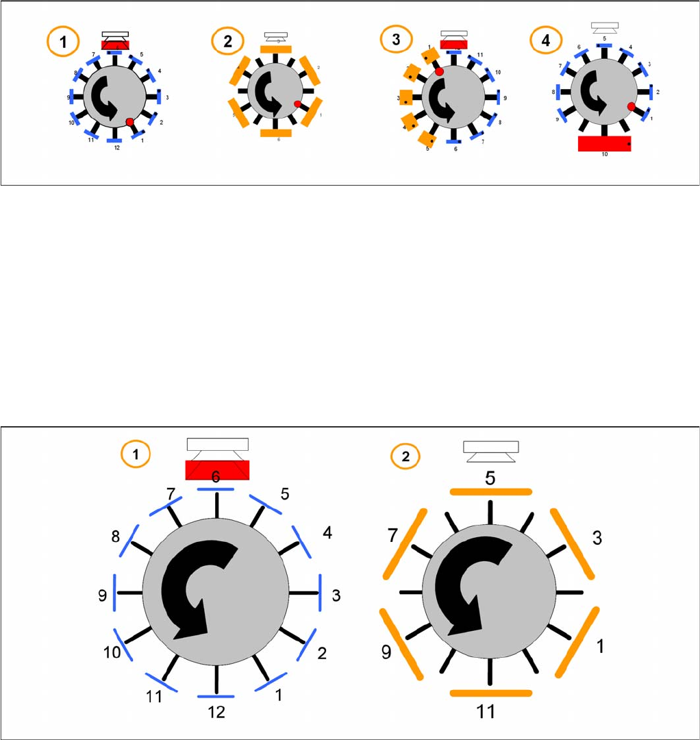
8.4.2.1 Collect&Place Mode
The Collect and Place Mode is the same mode as used by the existing C&P6/12 and C&P20 heads.
According to the number of available segments we pick up the component, center them and then place
them.
1. For the standard Collect and Place Mode, the max. component size is dependent on the camera
configuration (SST.29 & 38).
2. Components with a size up to 32 x 32 mm ( include the tolerance in SIPLACE Pro) can be picked up
and turned by the head. But they have to be centered with a stationary camera.
Collect, Pick and Place Head (CPP)
Placement Modes Pickup and Placement Cycle for CPP
Student Guide SIPLACE X-Serie and X4I SW70x (AL2) 294
Pick&Place Mode
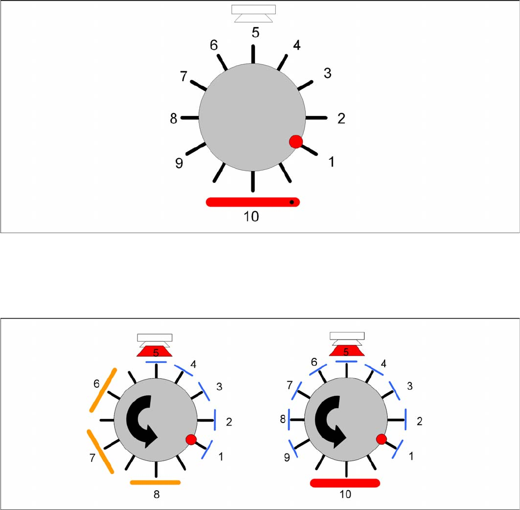
8.4.2.2 Pick&Place Mode
The Pick and Place mode is the same as used by the previous IC and TwinHeads. We pick up one
component with one segment, move to the stationary camera and center the components. The
component will be placed in the correct x/y- and angle-position.
Mixed Mode
8.4.2.3 Mixed Mode
According to the number of available segments the head will pick up the components and turn the them
through the head. Dependent on the component size and camera type the head will center the
components with the component camera whilst all other larger components will be centered with the
stationary camera. These components will be placed first according to some special features and
restrictions.
The follow special features and restrictions will be optimized in SIPLACE Pro:
▪ Component covered component sensor (Nozzle + Component height at 18,5mm)
▪ Dependency between Component size and weight and the camera types
▪ The placement shadow with components of max.11,5mm height.
▪ Travel profiles of the components (for Star, Dp- and Z-drives)
▪ Overlap Z and Star axis (e.g. 01005, big and flat components)