00194614-08 Trainingsdoku. SG X-Serie_X4i SW70x (AL2)_EN.pdf - 第483页
MTC2 MTC2 Calibration and Settings Adjustments feed axes 483 Student Guide SIPLACE X-Serie and X4I SW70x (AL2) ► Firmly tighten the cla mping screws and va rnish them with red sc rew loc king varnish. ► Check the belt te…
MTC2
Adjustments feed axes MTC2 Calibration and Settings
Student Guide SIPLACE X-Serie and X4I SW70x (AL2) 482
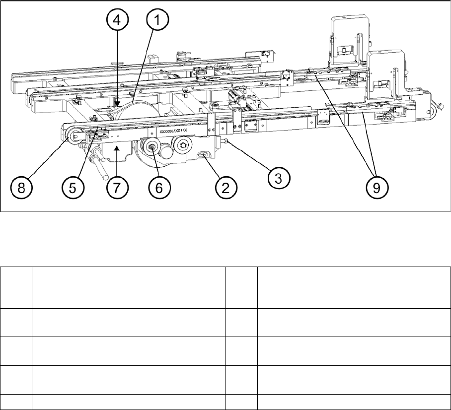
Checking and setting the belt tension
Legend
Preparat ions
Preparations
► Empty the MTC2 completely (see the User Manual).
► Undock the MTC2 from the SIPLACE station (see User Manual).
► Remove both cover plates between the rails of the feed axes.
Checking an d Setting the Driv e Belt
Checking and Setting the Drive Belt
► Carry out the relevant preparations (see "13.3.3.1.2 Preparations" [ ➙ 476]).
► Measure the belt tension with the belt frequency measuring device in the following way:
► Make the drive belt oscillate and measure the frequency in the middle of the sloping surface,
between the motor axis and the belt wheel (for the measuring point, see"13.3.3.1.1 Tools and
Equipment" [ ➙ 475]).
► You must set the belt tension if the measured frequency deviates from the nominal value (120 Hz ±
5 Hz):
► Turn the adjusting screw of the drive belt as far as it will go. Before doing this you will need to loosen
the lock nut.
► Loosen the two clamping screws on the mounting block of the motor.
► Use the adjusting screw to raise the belt tension (by turning in a clockwise direction) or lower it (by
turning in an anticlockwise direction), until the nominal frequency is achieved. Tighten the lock nuts
each time you measure the belt tension.
1 Drive belt (shown here for tower 2) 6 Eccentric axle of toothed belt with clamping
screw and flats for setting (shown here for
tower 1)
2 Motor mounting block with clamping
screws (shown here for tower 1)
7 Measuring point, toothed belt (shown here
for tower 1)
3 Adjustment screw, drive belt (shown here
for tower 1)
8 Outer deflection roll (shown here for tower
1)
4 Measuring point, drive belt (shown here for
tower 2)
9 Driver
5 Toothed belt (shown here for tower 1)

MTC2
MTC2 Calibration and Settings Adjustments feed axes
483 Student Guide SIPLACE X-Serie and X4I SW70x (AL2)
► Firmly tighten the clamping screws and varnish them with red screw locking varnish.
► Check the belt tension again.
► Secure the cover plates and dock the MTC2 onto the SIPLACE station (see the User Manual).
► Check the zero offset of the feed axis -> „Teach the zero point", if you have changed the belt tension.
Checking and setting the toothed belt
Checking and setting the toothed belt
► Carry out the relevant preparations (see "13.3.4.1.2 Preparations" [ ➙ 482]).
► Measure the belt tension with the belt frequency measuring device in the following way:
► Make the toothed belt oscillate and measure the frequency - from the underside of the belt - in the
middle, between the outer deflection pulley and the first deflection pulley of the drive (for the
measuring point, see "13.3.4.1.1 Tools and Equipment" [ ➙ 481]). Make sure that the driver is
approximately in its reference position.
► You must set the belt tension if the measured frequency deviates from the nominal value (70 Hz ± 2
Hz):
► Place the open-ended wrench on the setting flats of the eccentric axis.
► Loosen the clamping screw on the eccentric axis and maintain the position of the axis with the open-
ended wrench.
► Raise or lower the belt tension with the open-ended wrench (turning it in a direction depending on
the position of the eccentric axis), until the nominal frequency is achieved. Firmly tighten the
clamping screw each time you measure the belt tension and varnish it with red screw locking varnish.
► Check the belt tension again and make sure the screws are varnished with red screw locking varnish.
► Secure the cover plates and dock the MTC2 onto the SIPLACE station (see the User Manual).
► Check the zero offset of the feed axis -> „Teach the zero point", if you have changed the belt tension.
See also
13.3.3.1.1 Tools and Equipment [ ➙ 475]
Limit switch
13.3.4.2 Limit switch
Tools and accessories
Tools and accessories
▪ 1 set of Allen keys,
▪ 1 set of screwdrivers
Preparat ions
Preparations
► Check the zero offset -> "Check the zero point".
► Check the transfer position -> "teach transfer position".
Setting the limit switches
Setting the limit switches
► Move the feed axis into the transfer position (see Section ).
► Set the maximum position of the limit switch above its limit switch holder until there is a distance of
approximately 1 mm between the driver in the transfer position and the contact roller of the limit
switch.
► Move the feed axis into the zero position --> „Check the zero point“.
CAUTION
Before the limit switches are set, the zero offset and the transfer position must be checked (see
"13.3.2.2 Feed axis" [ ➙ 468]).
MTC2
Adjustments feed axes MTC2 Calibration and Settings
Student Guide SIPLACE X-Serie and X4I SW70x (AL2) 484
► Set the minimum position of the limit switch above its limit switch holder until there is a distance of
approximately 1 mm between the driver in the zero position and the contact roller of the limit switch
(approximately 10 mm on tower 2).
► Check the feed axis end positions --> „Check and calibrate the travel range end positions".
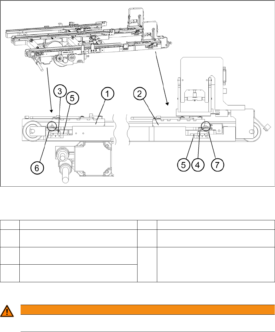
Setting the maximum and minimum positions of the limit switches (shown here for tower 1)
Legend
Light barriers
13.3.4.3 Light barriers
1 Driver at the transfer position 5 Limit switch holder
2 Driver at the zero position 6 Contact area driver/limit switch at
maximum position
3 Limit switch maximum position with contact
roller
7 Contact area driver/limit switch at minimum
position
4 Limit switch minimum position with contact
roller
WARNING
You may only check and calibrate the light barriers of the feed axis with the correct zero
positions, transfer positions and removal positions of the lifting and feed axes.