00194614-08 Trainingsdoku. SG X-Serie_X4i SW70x (AL2)_EN.pdf - 第397页
Modular Conveyor Conveyor Settings Setting the Laser Light Barrier for the Stoppe r Position 397 Student Guide SIPLACE X-Serie and X4I SW70x (AL2) Overview Laser light barrier Legend 1. Laser receiver 2. Laser diode 3. S…
Modular Conveyor
Setting the Laser Light Barrier for the Stopper Position Conveyor Settings
Student Guide SIPLACE X-Serie and X4I SW70x (AL2) 396
Setting the Pn eumatic Cylin der Proximity Swi tch on the Adj ustment Unit
11.3.3.2 Setting the Pneumatic Cylinder Proximity Switch on the Adjustment Unit
► Set any conveyor width. The adjustment units are positioned directly under the conveyor side.
► Start the I/O menu.
► Activate the pneumatic cylinder.
► Set the proximity switch on the pneumatic cylinder so that the LED (H35/H37 for TSP 301) (H64/65
for TSP 201) shines when connected.
Setting the Laser Light Barrier for the Stopper Position
11.3.4 Setting the Laser Light Barrier for the Stopper Position
Tools and equipment
▪ [00369205-xx] Setting gauge for laser light barrier / setting gauge laser light barrier
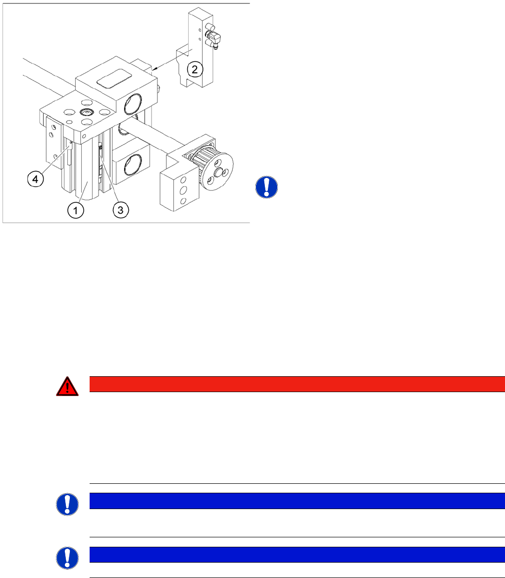
Overview of the proximity switches on the adjustment unit
for width adjustment
Legend
1. Pneumatic cylinder
2. Solenoid valve
3. Proximity switch for pneumatic cylinder (for "locking
pin up" recognition)
4. Proximity switch for adjustment unit(for conveyor side
recognition)
▪ The proximity switch (3) on the adjustment unit
cylinder should operate when the adjustment unit pin
is pushed out by the pneumatic cylinder and therefore
connected to the conveyor rail. This signal enables
the width adjustment motor.
NOTICE! The proximity switch on the pneumatic
cylinder is set when engaged.The proximity switch is off
when the cylinder is extended into free space.
DANGER
Laser class 2
The laser light barrier transmitter emits class 2 laser beams. You do not need to take additional
protective measures!
► You should never look into the laser beam, however.
► Do the adjustment of the LASER Diode Beam direction only from the rear side of the
LASER (left machine side).
NOTICE
The laser beam deflection has greatest effect at the maximum conveyor width, it should always
be calibrated at the maximum conveyor width.
NOTICE
After setting the laser light barrier you must check or re-teach the PCB reference corner!
Modular Conveyor
Conveyor Settings Setting the Laser Light Barrier for the Stopper Position
397 Student Guide SIPLACE X-Serie and X4I SW70x (AL2)
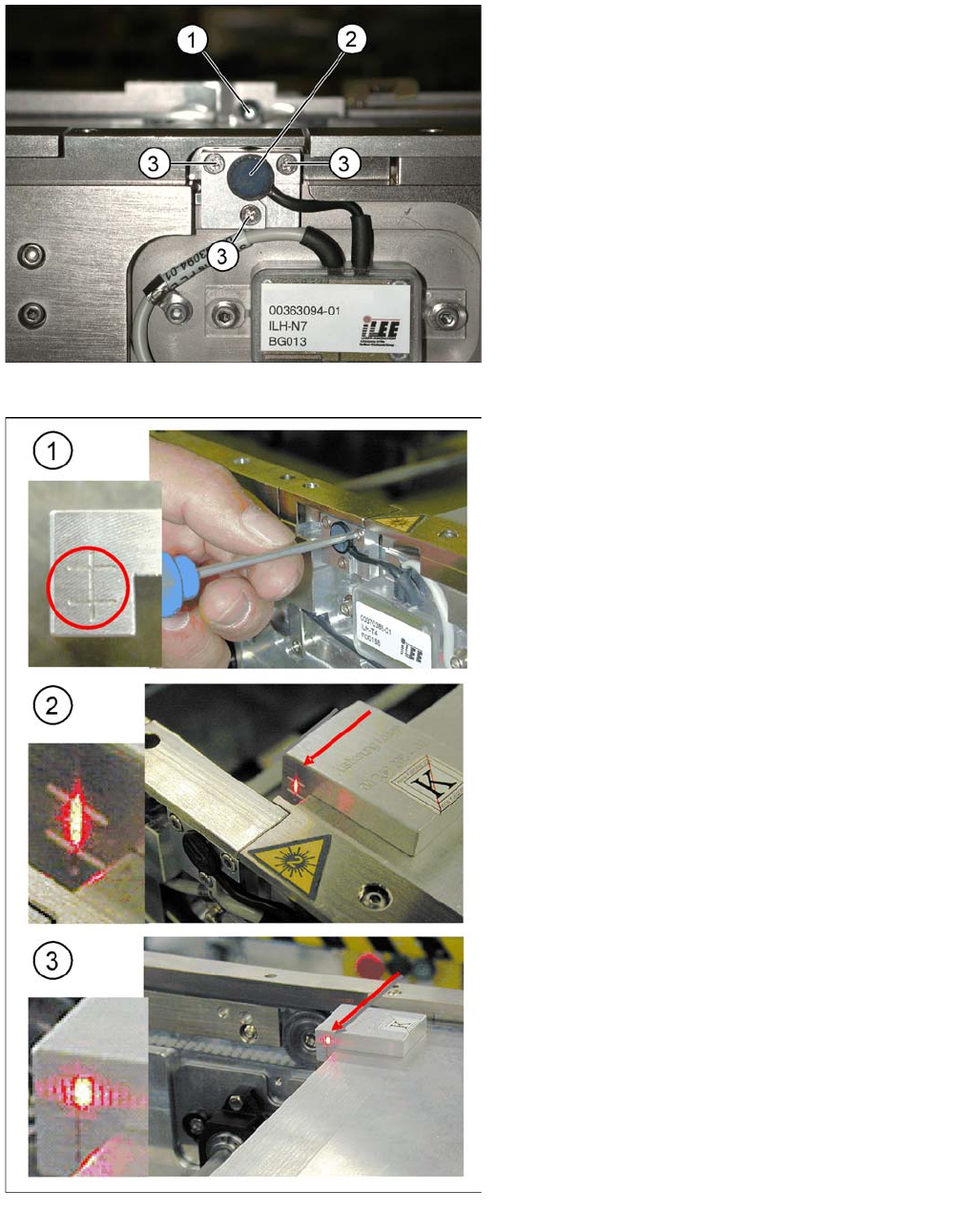
Overview
Laser light barrier
Legend
1. Laser receiver
2. Laser diode
3. Setting screws (3x)
Focussing the laser beam
Legend
1. Setting the laser light barrier
2. Minimum width
3. Maximum width
Procedure
► Set the maximum conveyor width.
► Select Safety mode switch on.
► Activate the relevant laser diode using the input/
output functions in the station software.
► Check the path of the laser beam with the help of the
gauge.
► With the help of the three setting screws, adjust the
laser beam to the center of the gauge cross (1).
► Now position the conveyor to minimum width (2) and
check the setting.
► Check the PCB reference corner and reteach, if
necessary.
Modular Conveyor
Light Barrier Function in the Placement Area Conveyor Settings
Student Guide SIPLACE X-Serie and X4I SW70x (AL2) 398
Light Barrier Function in the Placement Area
11.3.5 Light Barrier Function in the Placement Area
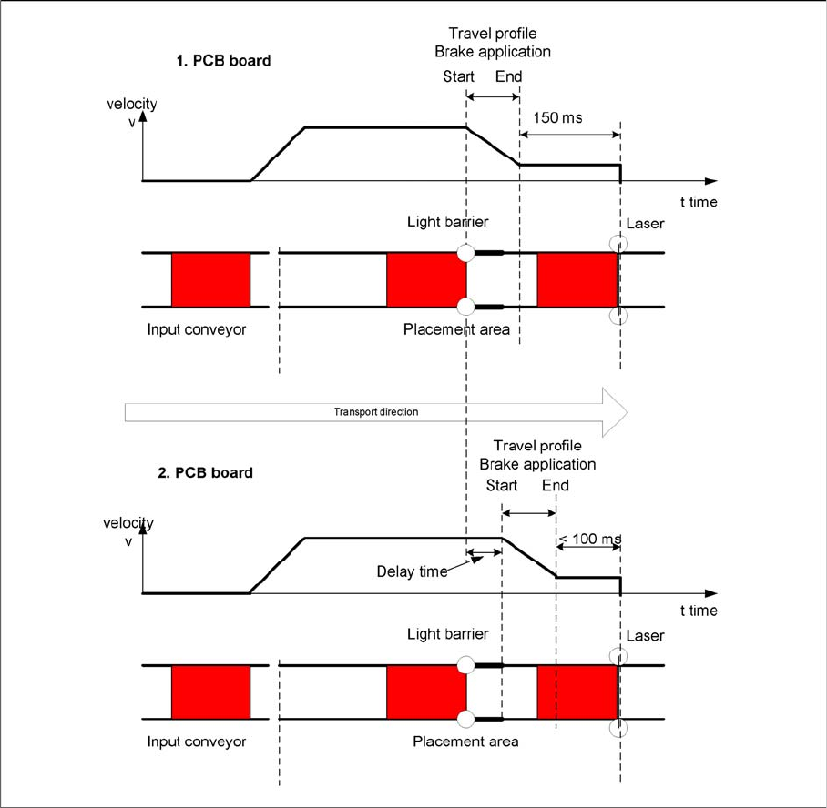
Diagrams PCB braking
Function:
▪ Switch on the laser light barrier.
▪ Starting the board braking procedure.
The light barrier recognizes the board and the software automatically teaches the creep speed for the
board. Once the travel profile for braking the PCB has begun (on time), the PCB will be reliably stopped
at the laser light barrier, after a maximum of 100ms.
Due to the automatic teaching at the beginning of the travel profile, the stopper position is always
reached in a constant time, irrespective of the board weight. The transport time remains constant.
Light Barrier Functions in In put, Intermedia te and Output Conveyors
11.3.6 Light Barrier Functions in Input, Intermediate and Output Conveyors
Function:
▪ Recognizing and stopping the PCB boards.