00194614-08 Trainingsdoku. SG X-Serie_X4i SW70x (AL2)_EN.pdf - 第424页
Head Modularity CPP Preperation Head Plate Student Guide SIPLACE X-Serie and X4I SW70x (AL2) 424 ► Seal the drilled holes on the C&P20A with these grub screws (3) . Seal the thr ead of the grub screw s with Loctite 5…
Head Modularity
Head Modularity C&P20A to CPP Head Calibration
423 Student Guide SIPLACE X-Serie and X4I SW70x (AL2)
► Dismantle the C&P20A placement head.
Protect the component sensor by fitting the red rubber hose onto the prisms and removing the
changeover table.
⇨ Remove the black compressed air hose from the distributor and from the head.
⇨ Loosen the flat ribbon cable from the head adapter but leave it on the head.
► Prepare the head plate as follows.
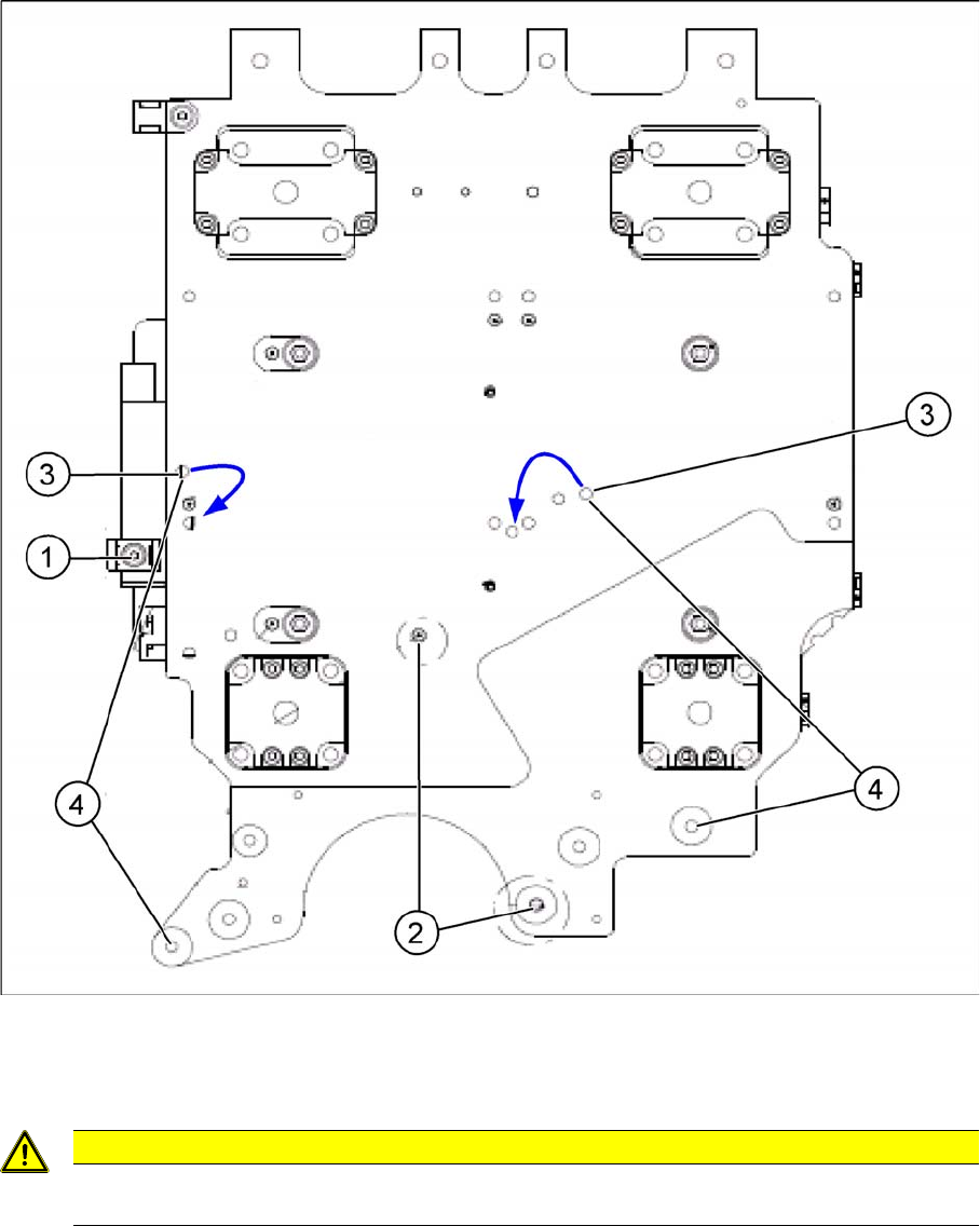
Preparing the X motor plate (head plate)
► Remove the cable holders (1).
► Check the length of the centering pins (2) before fitting a CPP head.
This may only extend 4.0 mm (tolerance: -0.2 mm) from the head plate.
► Remove the grub screws (3) from the head plate.
CAUTION
If the centering pins extend by more than 4.0 mm from the head plate, the incremental disk of
the star axis (glass) could be irreparably damaged during assembly of the CPP head!
Head Modularity
CPP Preperation Head Plate
Student Guide SIPLACE X-Serie and X4I SW70x (AL2) 424
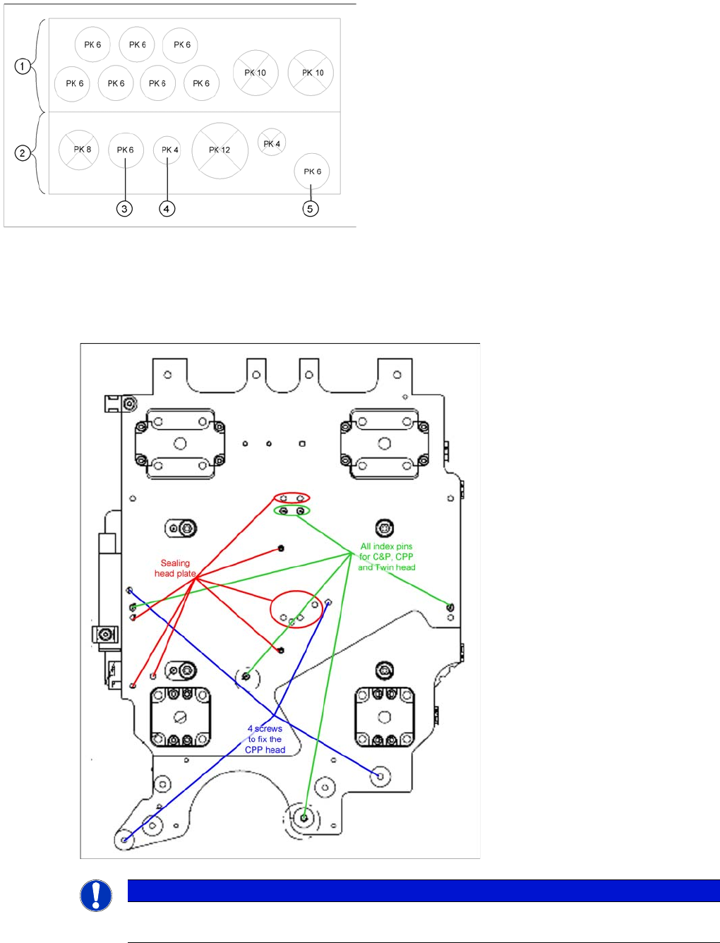
► Seal the drilled holes on the C&P20A with these grub screws (3).
Seal the thread of the grub screws with Loctite 511.
► Fit the CPP head with 4 M4x18 and 2.7 Nm screws.
Preperation Head Plate
12.7 Preperation Head Plate
CPP
12.7.1 CPP
Legend
1. Rear view
2. Front view
3. Connection for holding circuit
4. Connection for return cylinder
5. Connection for pressure control valve
► Connect the flat ribbon cable and the pneumatic
hoses and run correctly.
NOTICE
This head plate is fitted in machines from number B079 onwards. These differ only in the
extension fitted to the left side.
Head Modularity
Preperation Head Plate C&P20A
425 Student Guide SIPLACE X-Serie and X4I SW70x (AL2)
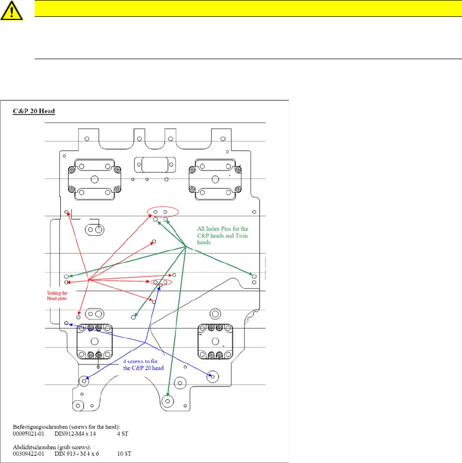
C&P20A
12.7.2 C&P20A
CAUTION
Before a CPP head is fitted, always check the length of the centering pins. These centering pins
may only extend out of the head plate by a maximum of 4.0 mm (tolerance: -0.2 mm). If these
are longer, the incremental disc for the star could be irreparably damaged.