00194614-08 Trainingsdoku. SG X-Serie_X4i SW70x (AL2)_EN.pdf - 第192页
Gantry PCB Boards on the Gantry Settings Student Guide SIPLACE X-Serie and X4I SW70x (AL2) 192 ▪ H8 P5V - 5 V p ower supply track sign als X axis --> r ed LED ON at error ▪ H1 B P5V – 5 V power su pply for digital swi…
Gantry
Settings PCB Boards on the Gantry
191 Student Guide SIPLACE X-Serie and X4I SW70x (AL2)
LEDs on the Head Interface
LEDs on the Head Interface
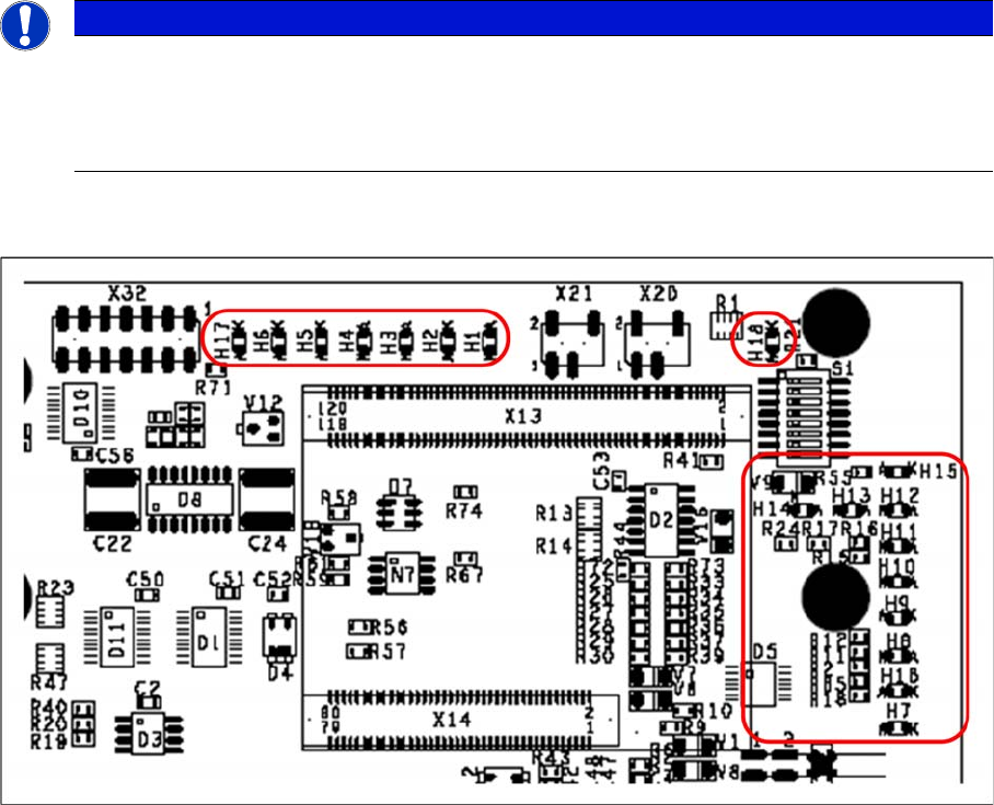
Head interface with status LEDs
LED H1-H6,H17,H18 (functional check)
▪ H17 SPI - Serial parallel interface (test)
▪ H6 D-ON - digital ON 5V DC/DC converter (power supply head interface, generated from the 24V)
▪ H5 H-OK - Head adapter board connected
▪ H4 C-In - CAN Internal (status off)
▪ H3 MRST - Main Reset (always off)
▪ H2 F-UC – Failure - UC test
F-UC flashes red after switching on the machine:
- eSW unable to perform one or more functions or initialization of a subsystem.
- flashes while the production power fail signal is active or 15V missing.
▪ H1 MP - Main Power fail, mean 5 V power supply being missing at the machine (e.g. CAN Bus)
▪ H18 1 Wire LED shows the high level on PIN 1 of 5V ON is green --> OK
LED H7- H15, H1B (LEDs for voltages)
▪ H14 Vcc - shows the output signal of the DC/DC converter (H6) +5 V
▪ H13 N15V – -15 V for TwinHead --> force measurement board (not for X4I)
▪ H15 P3,3V - Controller OK
▪ H12 P15V - Plus 15 Volt light barrier bottom C&P head
▪ H11 P24V - 24 V power supply (e.g.stepping motor)
▪ H10 AV ER - Failure 5 V
▪ H9 EN AN – 16 bit processor connected --> supply voltage OK
NOTICE
X4I
In the SIPLACE X4I machine, a mirrored version of the head interface C500 is fitted on gantries
2 and 4.
► Observe the different item number!
Gantry
PCB Boards on the Gantry Settings
Student Guide SIPLACE X-Serie and X4I SW70x (AL2) 192
▪ H8 P5V - 5 V power supply track signals X axis --> red LED ON at error
▪ H1 B P5V – 5 V power supply for digital switching --> outside tolerance
▪ H7 X Temp - Temperature monitoring X axis
DIP Switches on the Head Interfa ce
DIP Switches on the Head Interface
* Not all gantries may be available, depending on the machine type.
Vision Boa rd (Digital V ersion 02)
6.3.2.2 Vision Board (Digital Version 02)
The Vision processor board is fixed to the head interface of each gantry.
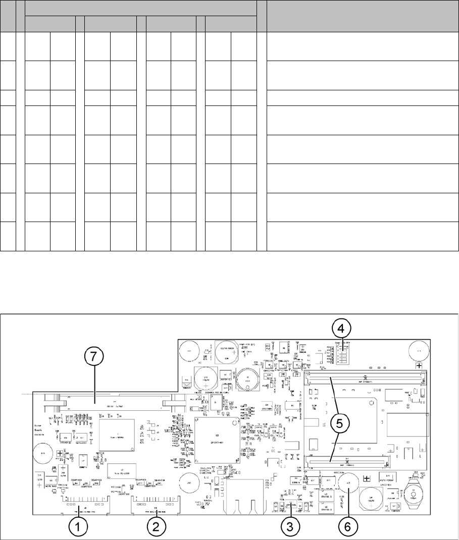
Vision board
S Setting for gantry* Comments
1 2 3 4
1 OF
F
ON OF
F
ON P0 – gantry ID0 address switch 1 -->
gantry
2 OF
F
OF
F
ON ON P1 – gantry ID1 address switch 2 -->
gantry)
3 X X X X X X X X OFF: Twin Head – ON: C&P head
4 OF
F
OF
F
OF
F
OF
F
Boot
5 OF
F
OF
F
OF
F
OF
F
Reset – CAN processor, 16 bit (TQM
module)
6 OF
F
OF
F
OF
F
OF
F
CAN_ID0
7 OF
F
OF
F
OF
F
OF
F
CAN_ID1
8 OF
F
OF
F
OF
F
OF
F
WP_EEPROM
Gantry
Settings PCB Boards on the Gantry
193 Student Guide SIPLACE X-Serie and X4I SW70x (AL2)
Legend
CAN Processor Board 16 Bit
6.3.2.3 CAN Processor Board 16 Bit
The 16 bit CAN processors are used for various functions on the following assemblies: (see also chapter
Communication and Control)
▪ Vision board: communication and control via CAN bus to station computer.
▪ Head processor board (C500), if a C&P head has been configured: control of head processes and
of vacuum generators
Description of 7 segment display (in normal mode the dot is flashing "."):
▪ After switching on, a "0" appears on the display
▪ Display "b" --> BIOS starts.
▪ Display flashes alternatively between "b" and "." --> no application available or unable to start
application.
▪ Display "-I" and "I-" --> application has been loaded and will now start.
▪ The dot "." on the display is flashing. --> the processor has booted and is ready for operation.
1 X8 Connector illumination and video
signals PCB camera
5 CAN processor 16 Bit (TQM module)
2 X3 Connector illumination and video
signals component camera
6 DC/DC converter 15 --> 5V for Vision
system.
3 LED‘s P15V - 15Volt / Vcc - Power supply
Vision board
7 Connector X4 – connection for video
signals to trailing cable
4 DIP switch
NOTICE
The DIP switch configuration for the gantry configuration is described in "6.3.2.4 Checking the
DIP Switches" [ ➙ 194].
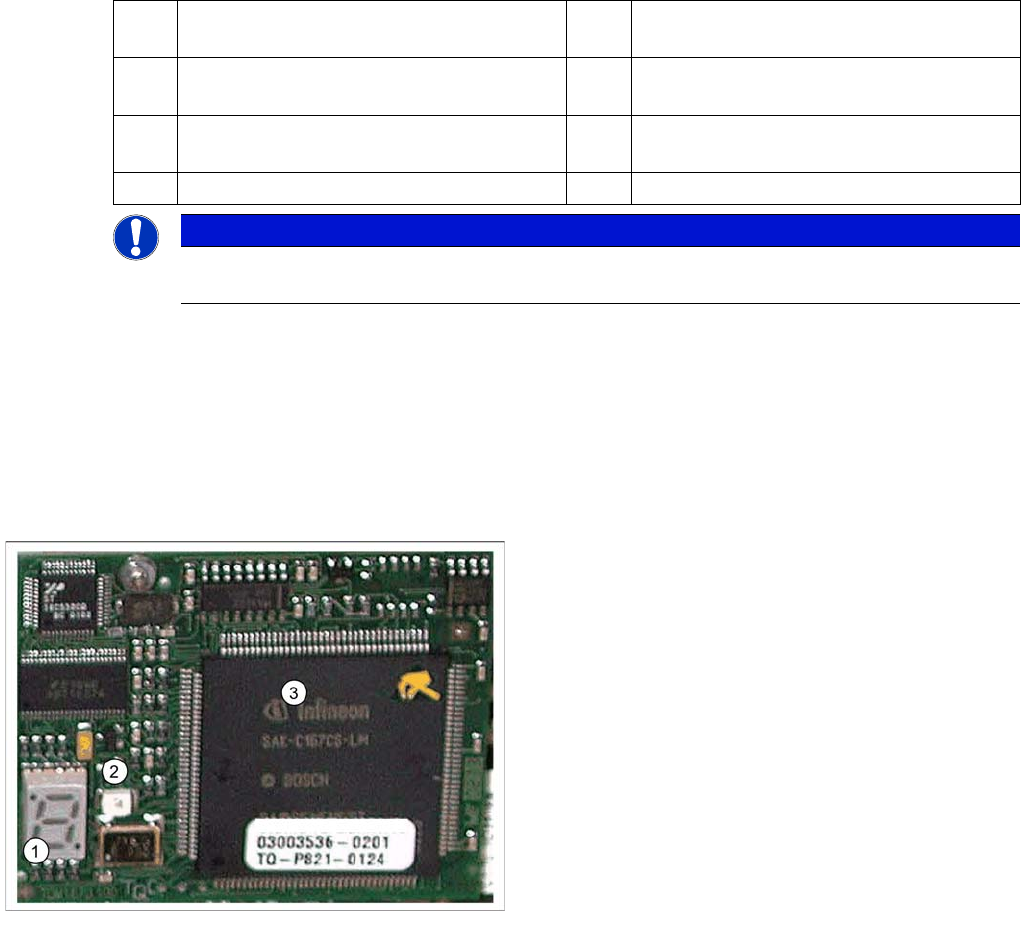
16 bit processor (TQM module)
Legend
1. 7 segment display
2. LED
The LED is red if you perform a manual RESET of the
processor.
3. 16 bit processor