00194614-08 Trainingsdoku. SG X-Serie_X4i SW70x (AL2)_EN.pdf - 第398页
Modular Conveyor Light Barrier Function in the Placement Area Conveyor Settings Student Guide SIPLACE X-Serie and X4I SW70x (AL2) 398 Light Barr ier Funct ion in th e Placement Area 11.3.5 Light Barrier Function in the P…
Modular Conveyor
Conveyor Settings Setting the Laser Light Barrier for the Stopper Position
397 Student Guide SIPLACE X-Serie and X4I SW70x (AL2)
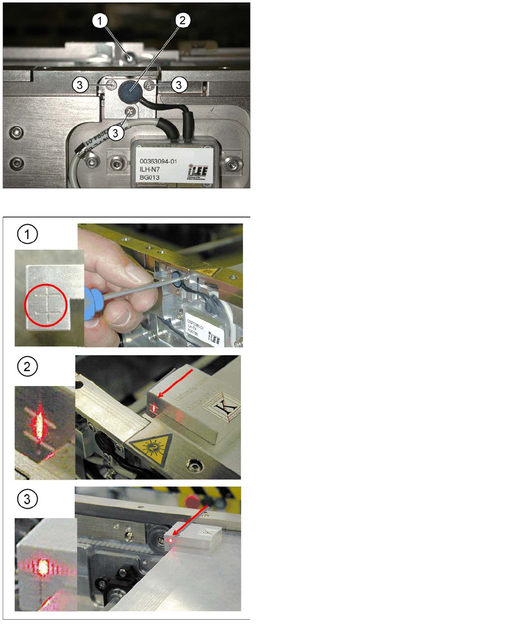
Overview
Laser light barrier
Legend
1. Laser receiver
2. Laser diode
3. Setting screws (3x)
Focussing the laser beam
Legend
1. Setting the laser light barrier
2. Minimum width
3. Maximum width
Procedure
► Set the maximum conveyor width.
► Select Safety mode switch on.
► Activate the relevant laser diode using the input/
output functions in the station software.
► Check the path of the laser beam with the help of the
gauge.
► With the help of the three setting screws, adjust the
laser beam to the center of the gauge cross (1).
► Now position the conveyor to minimum width (2) and
check the setting.
► Check the PCB reference corner and reteach, if
necessary.
Modular Conveyor
Light Barrier Function in the Placement Area Conveyor Settings
Student Guide SIPLACE X-Serie and X4I SW70x (AL2) 398
Light Barrier Function in the Placement Area
11.3.5 Light Barrier Function in the Placement Area
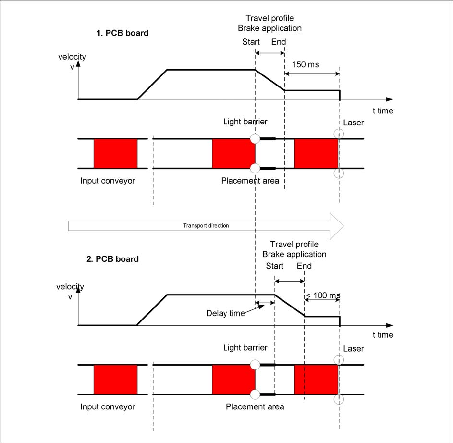
Diagrams PCB braking
Function:
▪ Switch on the laser light barrier.
▪ Starting the board braking procedure.
The light barrier recognizes the board and the software automatically teaches the creep speed for the
board. Once the travel profile for braking the PCB has begun (on time), the PCB will be reliably stopped
at the laser light barrier, after a maximum of 100ms.
Due to the automatic teaching at the beginning of the travel profile, the stopper position is always
reached in a constant time, irrespective of the board weight. The transport time remains constant.
Light Barrier Functions in In put, Intermedia te and Output Conveyors
11.3.6 Light Barrier Functions in Input, Intermediate and Output Conveyors
Function:
▪ Recognizing and stopping the PCB boards.

Modular Conveyor
Conveyor Settings Board Clamping Functions
399 Student Guide SIPLACE X-Serie and X4I SW70x (AL2)
▪ PCB monitoring in the input conveyer, meaning that
if a PCB is recognized in the input conveyer, this PCB will appear on the station GUI and the machine
will close the conveyor interface to the previous station. When using boards with cutouts, the light
barrier signal may extinguish and the interface to the upstream station may be opened although the
board has stopped. Then the next PCB would move into the input conveyer with the PCB still lying
in the input conveyer. The board monitoring function moves the board backwards and then forwards
again, until the light barrier switches.
Board C lamping F unctions
11.3.7 Board Clamping Functions
Function description:
▪ The PCB moves into the placement area, it is recognized by the light barrier, stops at the laser and
the lifting table moves up.
▪ Check PCB clamping: The transport motor in the placement area start again. If the PCB is clamped
correctly the motor current will rise up and reach a defined threshold value. Once the board has been
correctly clamped into place, the placement process will begin.
▪ If this threshold is not reached, the system assumes that the board is on its way to the intermediate
or output conveyor and has therefore not been correctly clamped into place.
▪ The station computer will issue the message "PCB not correctly clamped PA1 (PA2)". The process
can be repeated by pressing the "start button".
▪ The lifting table will move downwards, the board will be transported back and the stopper position
will be approached again.
NOTICE
The check whether a PCB is clamping correctly, is controlled with a motor current check of the
transport motor if the PCB board is clamped (Lifting table up). To check the function you could
put a distance plate under the conveyor side edge, so that the lifting table can not move to the
upper position.
The check is not performed if the option "Vacuum Tooling" is installed.