00194614-08 Trainingsdoku. SG X-Serie_X4i SW70x (AL2)_EN.pdf - 第278页
Collect, Pick and Place Head (CPP) Overview of Parts Overview Student Guide SIPLACE X-Serie and X4I SW70x (AL2) 278 Energy Trans mission Energy Transmission ▪ The e nergy transmission is done with the help of a split tra…
Collect, Pick and Place Head (CPP)
Overview Overview of Parts
277 Student Guide SIPLACE X-Serie and X4I SW70x (AL2)
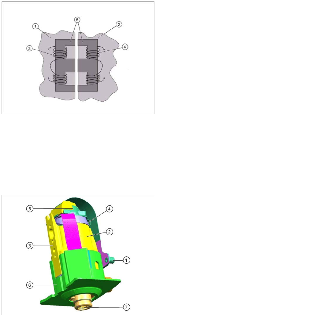
Energy Transmission
Energy Transmission
▪ Two transmission leads are needed to transmit the energy supply: P24V (1) and GND (2).
▪ Another lead (3) (sliding contact) forms the connection between the rotating part and the housing
ground (ESD protection).
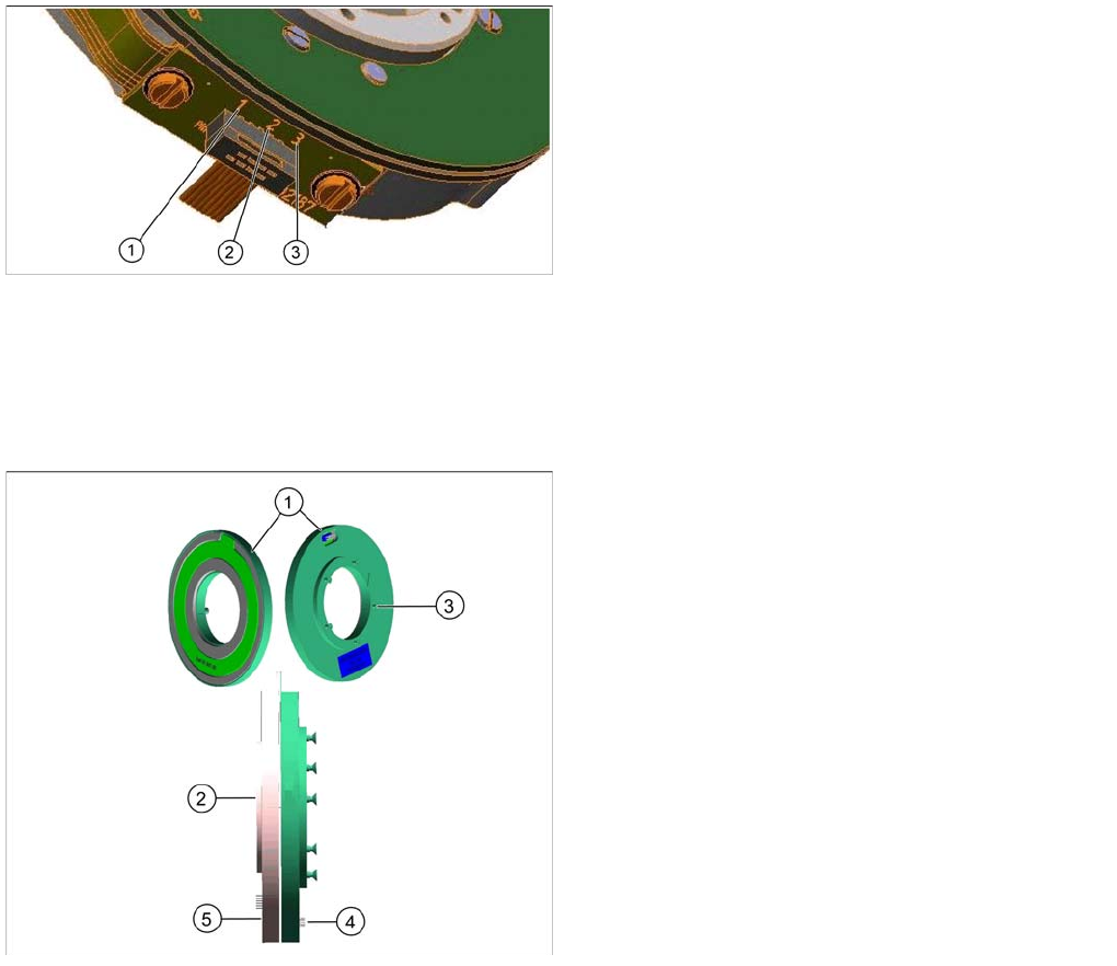
Contactless Energy Transformer (for CPP Heads from Version 05)
8.2.7.12 Contactless Energy Transformer (for CPP Heads from Version 05)
▪ The contactless energy transformer consists of two parts, a stator (1) and a rotor (2).
▪ Activating is done via an additional board that is located on the intermediate distributor 2 as a
piggyback board.
▪ The stator is fixed at the rear cover of the placement head, the rotating part, rotor, (2) is fixed to the
star frame via the terminal board.
▪ In the middle of the contactless energy transformer the transformer for contactless data transmission
is located.
Legend
1. P24V
2. GND
3. ESD protection
Legend
1. Stationary part (stator)
2. Rotating part (rotor)
3. Fastening screw at the rear cover (5x)
4. Power supply from the intermediate distributor to the
stator
5. Centering pin
6. Connector to SCS
Collect, Pick and Place Head (CPP)
Overview of Parts Overview
Student Guide SIPLACE X-Serie and X4I SW70x (AL2) 278
Energy Transmission
Energy Transmission
▪ The energy transmission is done with the help of a split transformer. One part is located on the rear
cover of the CPP head (stator) and the other part (rotor) is fitted to the valve terminal.
▪ Both transformer sections have coils. A.C. voltage from the stator side induces a magnetic field in
the transformer core, which then generates a.c. voltage on the rotor side. This power is used to
supply the SCS and to control the DP drives.
▪ A voltage of 24V is transmitted.
DP drive
8.2.7.13 DP drive
▪ The DP drive is responsible for turning the nozzles into the correct pickup position and the
component into the correct placement position.
▪ Vacuum and air blast to the nozzle are provided via the motor shaft of the DP axis.
▪ The complete DP drive and the linear guidance can be replaced during service work.
Legend
1. Rotor
2. Stator
3. Coil (secondary side)
4. Coil (primary side)
5. Split transformer ferrite core
Legend
1. The connector is fitted and screwed to the SCS
control unit.
2. Motor
3. Fixture surface for screwing the linear guidance into
place
4. Vacuum connection
5. Measuring system
Resolution: 278 digits per degree or
100.000 digits per revolution
6. Camera background (black) for DP drive
7. Nozzle interface
Collect, Pick and Place Head (CPP)
Overview Overview of Parts
279 Student Guide SIPLACE X-Serie and X4I SW70x (AL2)
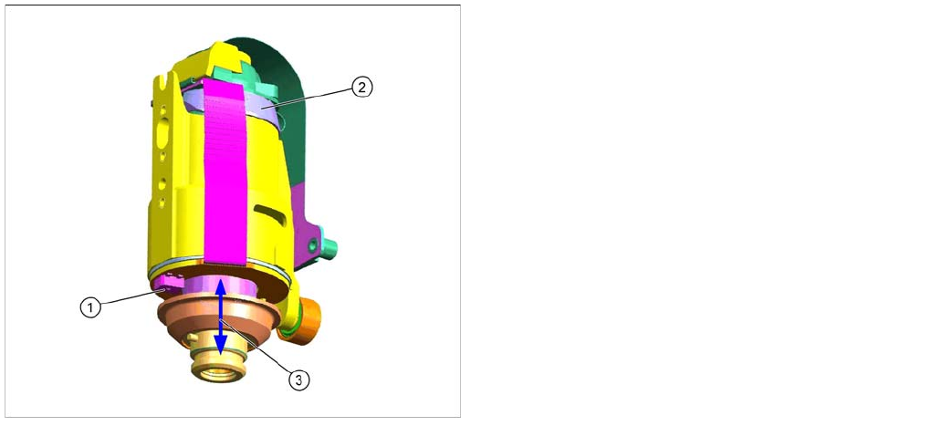
DP drive f unction
DP drive function
Measuring system function
The measuring system consists of a glass disk with increments. This glass disk is fixed firmly to the motor
shaft.
The read unit evaluates, multiplies and digitalizes these increments. This actual position value is
continuously compared with the prescribed nominal value by the control circuit.
Light barrier down
Each DP drive has its own light barrier down sensor. When the Z axis springs into place, this sensor
sends a signal to the axis controller board or HCU. The "light barrier down" signal is directly linked to the
measurement signal of the Z axis incremental encoder.
Legend
1. Light barrier down
2. Measuring system
3. Cushioning path for operating the light barrier down
DP drive function
The DP drives are controlled by the SCS board, in
accordance with the counter pulse and nominal value
(pickup angle, placement angle and correction angle
after Vision).
The feedback about the position of the DC motor is
monitored by an incremental measuring system.