00194614-08 Trainingsdoku. SG X-Serie_X4i SW70x (AL2)_EN.pdf - 第353页
Component Handling Changeover Table Setting the COT Height 353 Student Guide SIPLACE X-Serie and X4I SW70x (AL2) Special fitting screw on the chang eover table docking unit Setting th e COT Hei ght 10.1.4 Setting t he CO…
Component Handling
Changeover Table with One Hand Operation - Function Changeover Table
Student Guide SIPLACE X-Serie and X4I SW70x (AL2) 352
Fitting the Docking Unit
10.1.3.5 Fitting the Docking Unit
To guarantee the precise fit of the table feed device for accurate pickup of small components, the
docking unit on the inside of the machine is fixed with a special fitting screw. When fitting the docking
unit for the changeover table, make sure that this screw is fixed first, before the other screws.
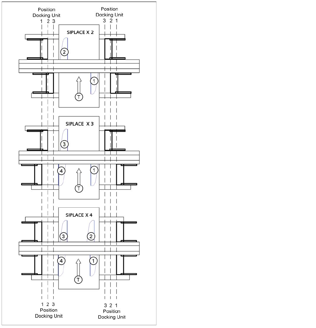
SIPLACE X2, X3 and X4
1. = Gantry 1
2. Gantry 2
3. Gantry 3
4. Gantry 4
T = transport direction
The docking unit of the MTC2 is always installed in
position 3 (see diagram).
Component Handling
Changeover Table Setting the COT Height
353 Student Guide SIPLACE X-Serie and X4I SW70x (AL2)
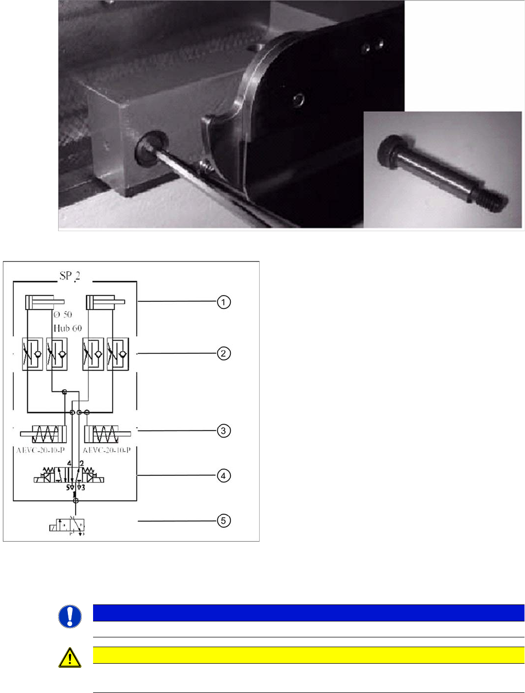
Special fitting screw on the changeover table docking unit
Setting the COT Height
10.1.4 Setting the COT Height
The changeover table can be adjusted to any height between 830 and 950 mm by removing the two pins
from the hollow shafts, which hold the table plate.
Pneumatic diagram docking unit
Legend
1. Pneumatic cylinder for moving the cam disks. This
means that the changeover table plate will move
43mm horizontally and 20 mm vertically into the
machine.
2. Throttle valves for adjusting the speed of the
pneumatic cylinders (time adjustment). Adjustment is
made without the changeover table and should take
approx. 2 seconds for docking and undocking.
3. Pneumatic cylinders for ejecting the COT during the
undocking procedure.
4. 5/2 way valve for controlling the pneumatic cylinder.
5. Safety valve in case of electrical faults
NOTICE
Adjustment of the COT height is in general identical for S and X tables.
CAUTION
Always use the screwed eyelet to fix the table plate, irrespective of whether you want to raise
or lower the component trolley.
Component Handling
Optional Extension on the Changeover Tables Changeover Table
Student Guide SIPLACE X-Serie and X4I SW70x (AL2) 354
X Table
10.1.4.1 X Table
Increas ing and Re ducing the COT He ight
10.1.4.2 Increasing and Reducing the COT Height
► Fix the screwed eyelet in the center of the table plate.
► A second person should lift the aluminum plate for X tables.
► Raise the changeover table plate slightly and knock the pins out of the left and right hollow shafts.
► Move the table plate to the correct height.
► Put back the 2 cotter pins (2) into the drilling hole of the sleeve shaft.
► Now, COT height is adjusted.
Optional Extension on the Changeover Tables
10.1.5 Optional Extension on the Changeover Tables
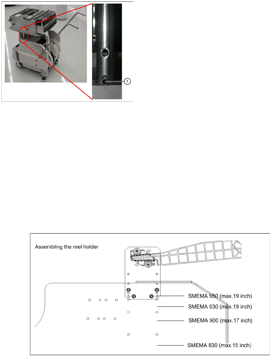
Additional R eel Holder o f the X Table
10.1.5.1 Additional Reel Holder of the X Table
The X table has 40 feeder locations. However, the tape reel container can only accommodate 30 tape
reels. An additional tape reel holder is therefore provided for the X table, as an option.
Additional reel holder X table
X table - adjusting the machine height
Legend
1. Hole for the cotter pins